
The Forward Converter
The forward converter is a type of DC-DC converter that is widely utilized in power supply applications due to its efficiency and simplicity. It operates by utilizing a transformer to transfer energy from the primary side to the secondary side while maintaining voltage regulation. The operational principle revolves around the switching of T1, which controls the flow of energy through the transformer.
When T1 is closed, the primary winding of the transformer is energized, creating a magnetic field that induces a voltage in the secondary winding. The conduction of diode D2 allows the current to flow to the load, charging the output capacitor while the choke stores energy. The linear increase in current through the choke is crucial for maintaining a stable output voltage.
Opening T1 interrupts the current flow in the primary winding, causing the magnetic field to collapse, which reverses the polarity of the magnetic components. This action blocks D2, and the choke L1 begins to release its stored energy to the load through diode D3. The careful design of the choke is essential to ensure that the current decreases linearly, preventing voltage spikes that could damage the circuit components.
The demagnetization of the transformer core is a critical aspect of the forward converter’s operation. If not addressed, core saturation can lead to inefficiencies and potential failure of the converter. The feedback mechanism via diode D1 allows for effective demagnetization by utilizing the magnetizing current to reset the core's magnetic state.
In terms of design considerations, the forward converter requires careful calculation of the turns ratio and duty cycle to optimize performance. The duty cycle is limited to a maximum of 50% in standard configurations, although advanced designs such as the two-switch forward and active-clamp forward converters can exceed this limitation. These variations provide additional flexibility in applications requiring higher efficiency or power output.
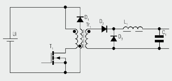
Overall, the forward converter represents a robust solution for DC-DC conversion, characterized by its direct energy transfer mechanism and effective management of magnetizing currents. Properly designed, it can deliver reliable performance in a variety of electronic applications.Diagram shows the basic construction of a forward converter. Whereas the energy is temporarily stored with the flyback converter before it is transferred to the secondary side, in the forward converter, energy is transferred directly between the primary and secondary sides. As an aid for understanding, the individual switching states in the s teady state system are examined. With the switch T1 closed, there is the same polarity at both dots of the transformer circuit diagram so that the diode D2 is conducting. In accordance with the function of the transformer (Chapter I/1. 9) the current transformed from the secondary side flows on the primary side and the linearly increasing magnetizing current.
The transformed input voltage is applied to the secondary winding. This serves to charge the choke. A linearly increasing current flows through the choke and the load. If the switch T1 is now opened, the current cannot continue to flow on the primary side. The polarity in the magnetic components reverses so that D2 is blocked on the secondary side. The choke L1 now transfers the stored energy to the load (or the output capacitor) via D3. The current through the choke again decreases linearly. The core of the transformer has been magnetized by the magnetization current. The remanence of the core material would cause the core to saturate within a few switching cycles. So it has to be demagnetized after each switching period. Various techniques have been used for this purpose. The simplest option is presented in Figure 3. 179. During the shutdown phase the magnetizing current is fed back via diode D1 through the auxiliary winding. The number of turns used for the auxiliary winding is usually the same as that used for the primary winding.
This means that the same time is required for demagnetization as for magnetization. The converter can therefore be driven at a maximum duty cycle of 50%. Further possibilities for demagnetization are presented by the forward converter with two switches (two-switch forward) (Figure 3. 180) and the forward converter with active clamping (active-clamp forward) (Figure 3. 181). In the case of the two-switch forward, the core is demagnetized via both diodes so that no auxiliary winding is required.
For the active-clamp forward, the capacitor on the transformer generates a higher negative voltage, so that the demagnetization is achieved in a shorter time. This means that duty cycles higher than 50% are possible. As previously mentioned, the forward converter behaves like step-down converter with pre-switched voltage transformation.
The following relationship is therefore given between the turns ratio and the duty cycle: This allows the wire thickness for the windings and the copper losses to be determined. Another auxiliary winding may have to be fitted depending of the demagnetization circuit. As it is only the magnetizing current that flows through it here, a relatively fine wire is sufficient.
The same approach is taken towards dimensioning the output choke as with the step-down converter. The same relationship exists between the ripple, frequency and inductance: 🔗 External reference
Related Circuits
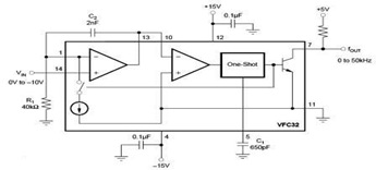
The circuit diagram of a voltage-to-frequency (V/F) converter is presented, designed to handle negative input voltage. It employs the VFC32 voltage-to-frequency converter, which is commonly utilized in various applications. The V/F converter circuit is essential in converting an analog voltage...
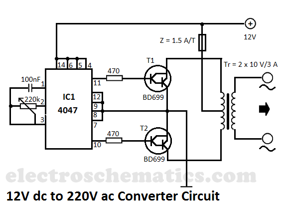
This DIY 12V to 220V voltage converter is built with the CMOS 4047, which serves as the main component of this compact voltage converter that transforms 12V DC into 220V AC. The 4047 is configured as an astable multivibrator,...
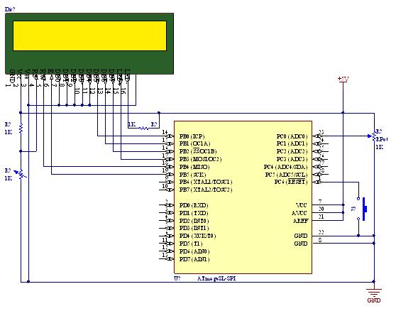
A straightforward tutorial on utilizing the ADC (Analog to Digital Converter) unit of the AVR microcontroller, demonstrated with the Atmega8, including a circuit diagram and code examples. The ADC unit in the Atmega8 microcontroller is a crucial component that allows...
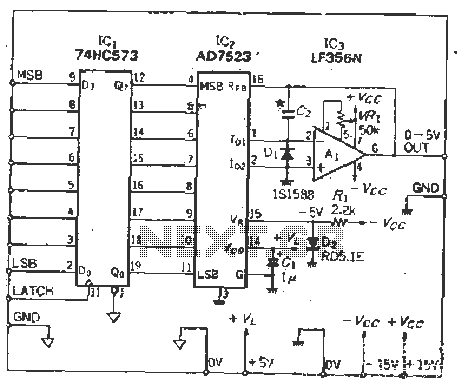
The IC latch is utilized to hold the digital data when the clock signal rises. The configuration includes a holding data port AD7s23, a thin film resistor ladder, and a switch that together form an 8-bit Digital-to-Analog Converter (DAC)....
Any step-down DC-DC converter can be utilized as an inverter without modifications to the operating schematic. The only differences between the standard step-down application and the inverting operation are the labels of the connection points. The step-down VOUT is... A...
The TDA8444 is a digital-to-analog (D/A) converter integrated circuit (IC) produced by Philips. It is designed to convert digital signals into analog signals. The TDA8444 IC utilizes a 16-pin dual in-line package, with specific pin functions and data outlined...
Warning: include(partials/cookie-banner.php): Failed to open stream: Permission denied in /var/www/html/nextgr/view-circuit.php on line 713
Warning: include(): Failed opening 'partials/cookie-banner.php' for inclusion (include_path='.:/usr/share/php') in /var/www/html/nextgr/view-circuit.php on line 713