
The Itsy-Bitsy USB Lamp
To construct the Itsy Bitsy USB Lamp, a USB cable with at least one male plug is required. These cables are widely available and can be purchased at a low cost. For instance, a local computer shop sells a 1m USB extension cable for $6, but better deals may be found at computer fairs or swap meets. A practical tip is to collaborate with a friend to purchase a male-to-male USB cable, cut it in half, and each build a lamp for half the cost.
To begin assembly, strip approximately 5cm of the outer insulation and shield from the end of the USB cable. Standard USB cables contain four wires: red, white, black, and green (along with the shield). The green and white wires, which carry data, can be trimmed back as they are unnecessary for this project. It is advisable to use heat shrink tubing over the ends of the trimmed green and white wires to prevent any shorts. The red and black wires should have about 2mm of insulation removed from their ends.
Next, open the in-line 3AG fuse holder and remove the internal components. Only the two plastic parts are needed. Slide the longer piece over the end of the wire, smallest end first, ensuring a snug fit. It may be necessary to drill or ream out the hole slightly to accommodate the wire. Similarly, this adjustment may be required for the other piece of the fuse holder for the LED.
The anode lead (longer lead) of the white LED should be cut to about 3mm, and both leads of a 47-ohm resistor should also be trimmed to approximately 3mm. Solder one lead of the resistor to the anode of the LED. The 47-ohm resistor will have a color code of yellow, purple, black, gold (or yellow, purple, black, gold, gold if it is a 5-bander) and can be soldered in either orientation.
To insulate the connection, cut a length of spaghetti insulation (or small plastic tubing) long enough to cover the resistor and its leads, and slide it over the resistor. Heat shrink tubing can also serve this purpose. Cut two short lengths of insulation (around 5mm) and slide them over the red and black wires of the USB cable. Solder the red wire to the resistor end and the black wire to the LED cathode.
Once the soldering is complete, slide the 5mm lengths of insulation over the solder joints to prevent shorts. Although it is advisable to include a fuse for safety, the USB port itself will limit current in the event of a short, making a fuse unnecessary.
Before proceeding, it is crucial to verify that all connections are correct and that there are no potential shorts, especially between the USB cable leads. Failure to ensure this could result in damage to the computer. With the computer powered on, plug the USB connector into the USB port. If everything is functioning correctly, the white LED should illuminate brightly. If it does not, check for shorts or open circuits.
Finally, slide the fuse holder up the USB cable, pushing the components inside until only the LED and about 3mm of its leads are visible. Attach the shorter end of the fuse holder onto the longer piece so that the LED protrudes slightly from the hole. Twist the fuse holder end onto the body to secure it in place. The Itsy Bitsy USB Lamp is now complete and ready to provide illumination wherever needed around the computer by simply plugging it into the USB port.It plugs into the USB port and is just the shot for checking motherboard switch and jumper settings. Many readers will remember a commercial product of a few years ago, the "Itty Bitty Book Light". It was designed to clip over the top of a book to give just a tiny light on the page when, for example, you were reading in bed and didn`t wish to dist urb your partner. Times have changed. Now we`re all working with computers. Many`s the time I`ve been trying to look deep inside a computer and wished it was a bit brighter so I could read type numbers, see plug and socket orientations, check board seating, and so on. Sometimes, even a torch won`t work because it`s too big to get really deep down. You can`t get that light where you really need it. Well, here`s the answer. We`ve called it the Itsy Bitsy USB Lamp. It is such a delightfully simple idea we`re wondering why no-one ever thought of it before. It started life (and continues) as a student project at Massey University in Wellington, New Zealand - and in fact was submitted to us by the lecturer, Stan Swan.
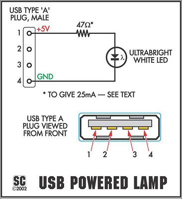
When we say simple, we mean it: just a USB plug on a suitable length of cable, a super bright white LED and a series resistor to limit LED current. The LED and resistor are housed in an in-line fuse holder (without its innards!) which makes a superb little "wand" and also protects the electronics, such as they are.
In all modern computers, you will find at least one, usually two and often four USB ports. USB stands for Universal Serial Bus, and is one of the latest incarnations of methods to get information in and out of your computer. We`re not particularly interested in information transfer as such. But we are interested in the fact that the USB port offers power to external devices - +5V is available on pin 1 (0V on pin 4).
Up to 100mA is available from the USB port - far more than we need for this little application. That`s the reason for the series resistor. A 47 © resistor will limit the current to about 25mA - just about ideal. The first thing you will need is a USB cable with at least one male plug on it. These are becoming fairly common and you should be able to pick one up for just a few dollars. A local computer shop has a 1m USB extension cable for $6 but you could well do better than this at computer fairs, swap meets, etc. Here`s a tip: get together with a mate and buy a male-to-male USB cable. Cut the cable in half and you can both build an Itty Bitty USB Lamp for half the cost! Strip back about 5cm of the outer insulation and shield from the "bare" end of the USB cable. Normal USB cables have four wires: red, white, black and green (as well as the shield). The green and white carry the data - we don`t need them so they can be trimmed right back (make sure the wires inside their insulation are not exposed at all).
A tiny length of heatshrink tubing over the ends of the green and white wires will ensure that there cannot be shorts, either to themselves, to the shield wire or to the red or black wires. Carefully bare about 2mm of the insulation on the red and black wires. Before we go too much further, open up the in-line 3AG fuse holder and remove the wires and spring inside.
All we want are the two plastic bits. Slide the longer of the two pieces over the end of the wire, smallest end first. (You may need to drill or ream out the hole a little to accommodate the wire but don`t go overboard! Similarly, this might be necessary on the other bit of fuseholder to accommodate the LED when we come to it shortly. ) The photograph shows this well. Slide the fuseholder down far enough so it is out of the way. Cut the anode lead (the longer lead) of the bright white LED to about 3mm long. Similarly, cut both leads of a 47 © 1/4W (or even 1/8W) resistor to about 3mm long and carefully solder one lead of the resistor to the anode of the LED.
The 47 © resistor will have a colour code of yellow, purple, black, gold (or yellow, purple, black, gold, gold if it`s a 5-bander). It can be soldered either way around. Cut a length of spaghetti insulation (or some tiny plastic tubing) long enough to cover the resistor and its leads, then slide this over the resistor so the connection to the anode is completely insulated.
Heatshrink tubing may also be used for this purpose, but is not essential. Cut another two short lengths of insulation (say 5mm) and slide them over the red and black wires of the USB cable. Solder the red wire to the resistor end and the black wire to the LED cathode. By the way, spaghetti insulation is not pasta. Now slide the 5mm lengths of insulation over the solder joints - it is important that the bits cannot short out to each other when scrunched up inside their fuseholder "home".
Strictly speaking, this assembly should be fused in case of a short but even it there is a short the USB port will limit the current available. So no fuse! (But it`s better not to have a short anyway!). Before going any further, check and check again that everything is as it should be. Most of all, make sure that there is no possibility of any shorts from one lead of the USB cable to another - particularly the green and white (data) wires.
(Failure to do this could damage your computer). With your computer on, plug the USB plug into the USB socket. If everything is OK, the white LED should glow brightly. If not, check for shorts or open circuits. Slide the fuseholder back up the USB cable, pushing everything inside it until only the LED and abut 3mm of its leads are emerging. Slide the other end of the fuseholder (the shorter end) onto the longer piece so that the LED just pokes the top of its head out the hole (flush with the hole is fine).
Twist the fuseholder end onto its body to lock it in place. And that`s it. Now when you need a bright light anywhere around your computer - all you have to do is plug it in to the USB port! 🔗 External reference
Related Circuits
This document serves as a resource for developers who are new to Texas Instruments (TI) ARM-based processors, as well as for seasoned developers seeking to deepen their understanding of the different ARM architectures. It starts with an overview of...
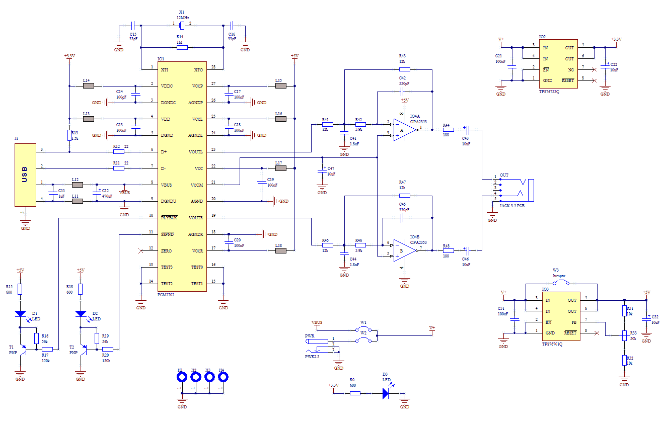
If you use great IC PCM2702 from BURR BROWN / Texas Instruments you can create a fully functional USB sound card. This sound card can be powered from USB port and has one stereo output. You don’t need to...

The FTDI DLP-USB245M is a USB-to FIFO interface module that simplifies the control of multiple stepper motors by a PC. The FTDI DLP-USB245M module is designed to facilitate communication between a PC and various electronic devices, specifically enabling the control...
After completing several V-USB tutorials, the next project undertaken was to create a compact USB HID keyboard device that types a password stored in EEPROM each time it is connected. The password can be regenerated by pressing the CAPS...
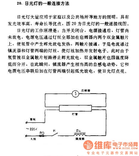
The general connection method for fluorescent lamps is utilized in residential and public lighting applications due to their luminous efficiency and long service life. The general wiring diagram for the lamp is illustrated in Figure 20. The working principle...
The purpose of this circuit is to power a lamp or other appliance for a specified duration (30 minutes in this case) and then automatically turn it off. This functionality is particularly useful for reading in bed at night,...
Warning: include(partials/cookie-banner.php): Failed to open stream: Permission denied in /var/www/html/nextgr/view-circuit.php on line 713
Warning: include(): Failed opening 'partials/cookie-banner.php' for inclusion (include_path='.:/usr/share/php') in /var/www/html/nextgr/view-circuit.php on line 713