
The motorcycle anti-theft alarm (3)
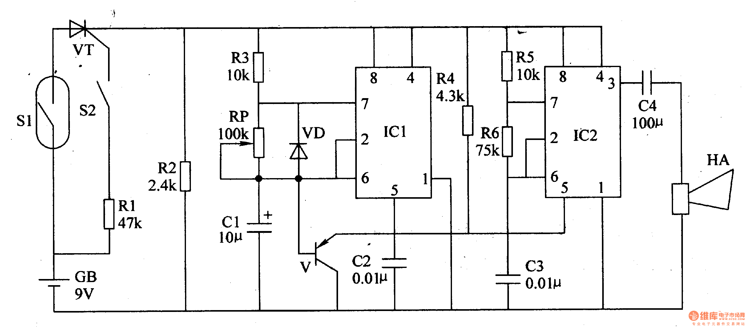
The motorcycle anti-theft alarm system is designed to enhance the security of motorcycles by detecting unauthorized movement. The core component of this system is the 555 timer IC, which operates in a monostable mode to generate a time-delayed output signal. This signal is used to trigger the alarm when the motorcycle is tilted or lifted, indicating potential theft.
The trigger circuit typically includes a tilt sensor or a vibration sensor, which detects the motion of the motorcycle. When the sensor is activated by vertical movement, it sends a signal to the 555 timer IC. The timer is configured to produce a high output for a predetermined duration, which can be adjusted based on the user's preference. This output activates the alarm circuit, which may consist of a loudspeaker or siren to alert nearby individuals of the theft attempt.
The alarm circuit can also include additional features such as LED indicators to visually signal the alarm status or a relay to control other security devices. Power supply considerations are crucial; the circuit can be powered by the motorcycle's battery, ensuring that it remains operational even when the motorcycle is parked.
In summary, the motorcycle anti-theft alarm circuit using a 555 timer is an effective solution for enhancing motorcycle security. Its simple design allows for easy installation and customization, making it accessible for a wide range of users looking to protect their vehicles from theft.The motorcycle anti-theft alarm which uses the 555 time-base integrated circuit is introduced in this article, and it can send out the alarm when the thief is moving the motorcycle vertically. The principle of the circuit The motorcycle anti-theft alarm circuit is composed of the trigger circuit and the alarm circuit, as the figure 7-85 shows.The trigger..
🔗 External reference
Related Circuits

The circuit utilizes the HL-169B voice alarm integrated circuit (IC). It is designed for use in security applications, including glass doors, car doors, and windows, to act as a burglar alarm. When a thief applies force to these items,...

This circuit is capable of generating up to 1 W of audio power to drive a speaker or horn. When the CDS cell is exposed to light, its resistance decreases, activating NOR gate (a). This activation causes gates (a)...
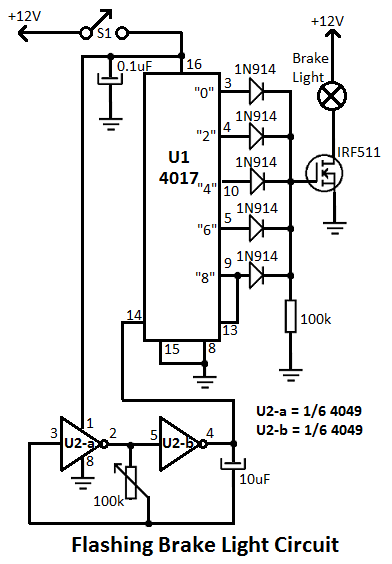
This flashing brake light circuit is designed for motorcycles. When the brake light switch S1 is closed, power is supplied to U1 and U2. The circuit utilizes two inverters from U2. The flashing brake light circuit operates by utilizing a...
This circuit project automatically activates a night lamp when the bedroom light is turned off. The lamp stays illuminated until the light sensor detects daylight. The circuit operates using a light-dependent resistor (LDR) as the primary sensor to detect ambient...
Construct a basic power failure alarm monitoring system utilizing an AC relay that activates a buzzer when the mains power supply is interrupted. The proposed power failure alarm monitoring system is designed to provide an audible alert during a loss...
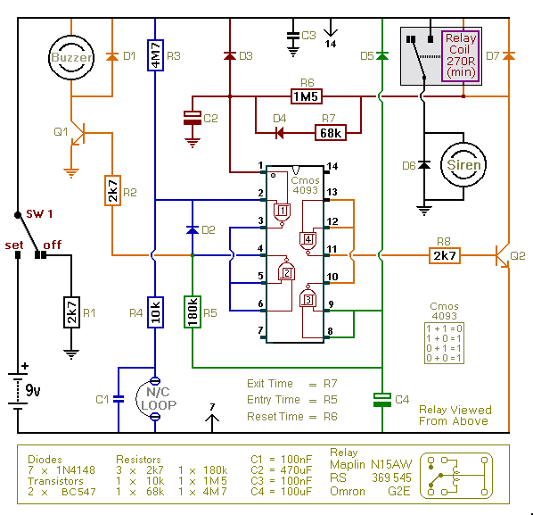
This is an improved version of the basic Garage/Shed Alarm. The Entry and Exit delays have been extended to approximately 30 seconds, and a timed Siren cut-off along with an automatic reset feature has been added. Additionally, the LED...
Warning: include(partials/cookie-banner.php): Failed to open stream: Permission denied in /var/www/html/nextgr/view-circuit.php on line 713
Warning: include(): Failed opening 'partials/cookie-banner.php' for inclusion (include_path='.:/usr/share/php') in /var/www/html/nextgr/view-circuit.php on line 713