
High-Output Pulsed-Tone/Light-Activated Alarm Circuit

The circuit operates on the principle of light-dependent resistance, utilizing a Cadmium Sulfide (CDS) cell as a light sensor. The decrease in resistance of the CDS cell under illumination triggers the NOR gate configuration, which is fundamental to the operation of this audio signal generator. The output from the NOR gates produces a square wave oscillation at a frequency of 10 Hz, which serves as the modulation frequency for the subsequent oscillator stages.
The 1-kHz oscillator is composed of additional gates (c) and (d), which are configured to generate a stable tone that is pulsed in accordance with the 10-Hz modulation signal. This creates an audio output that is not only tonal but also rhythmically varied due to the low-frequency modulation.
Transistors Q1 and Q2 serve as the amplification stage of the circuit. Q1 is configured to enhance the signal from the oscillator, while Q2, specifically the 2N3055 model, is a power transistor capable of handling higher currents required to drive a speaker. This configuration allows the circuit to efficiently convert low-level audio signals into sufficient power to drive typical speakers or horns, achieving the desired output power of up to 1 W.
Overall, this circuit exemplifies a simple yet effective design for audio signal generation and amplification, leveraging light sensitivity to control the audio output while maintaining a low-frequency modulation for dynamic sound production. This circuit can produce up to 1 W of audio power to drive a speaker or horn. When the CDS cell is struck by light, its resistance decreases thus activating NOR gate (a) thereby causing (a) and (b) to produce a low-frequency (10-Hz) square wave. This pulses the 1-kHz oscillator (c) and (d), causing it to generate a pulsed 1-kHz tone at a 10-Hz rate.
Ql and Q2 amplify this signal. Q2 (2N3055) drives the speaker. 🔗 External reference
Related Circuits
The circuit of an FM Tracking Transmitter Circuit or Remote Control Transmitter Circuit is explained using a 555 IC and 2N4392 transistors. The FM Tracking Transmitter Circuit utilizes a 555 timer integrated circuit (IC) configured in astable mode to generate...
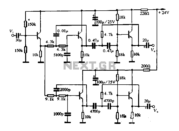
This article describes a band-pass filter circuit diagram utilizing transistors. A band-pass filter is an essential electronic circuit that allows signals within a certain frequency range to pass while attenuating frequencies outside that range. The circuit typically consists of a...
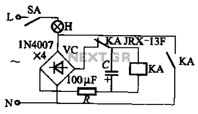
The circuit illustrated in Figure 13-3 consists of two configurations: (a) a DC power supply and (b) an AC power supply. Both configurations are utilized to control a relay. The flash frequency of the relay is determined by the...

This circuit is designed for differential analog circuit switches. The FM1208 monolithic dual differential multiplexer is utilized in applications where the RDS (ON) must be closely matched. The RDS (ON) for the monolithic dual multiplexer operates with a precision...
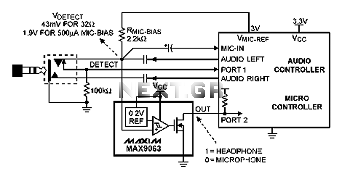
A headphone type detection circuit is illustrated in the attached figure. The 2.2k RMIC-BIAS resistor connected to the audio controller provides a low-noise reference voltage (VMIC-REF). When the audio jack is inserted, the VMIC-REF voltage through RMIC-BIAS is applied...
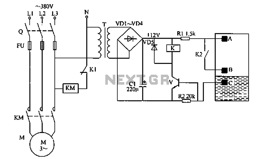
The liquid level automatic controller circuit consists of a power circuit, a level detection circuit, and a control implementation circuit. The power circuit is formed by a power transformer T, rectifier diodes YD1 to VD4, and a filter capacitor...