
the octal phono preamplifier
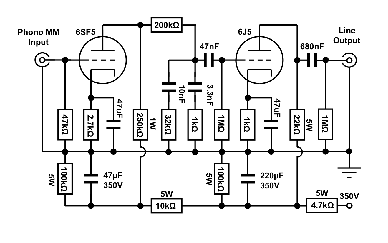
The circuit operates in a straightforward RC-coupled configuration. The 6SF5 has a 250k plate resistor and a 2.7k cathode resistor, resulting in a bias that divides the plate voltage approximately equally across the plate resistor and the tube. A similar configuration is used for the 6J5, which has a 22k plate resistor and a 1k cathode resistor. The 6SF5 idles at around 0.6mA and draws approximately 5mA. Both cathode resistors are bypassed with capacitors to maximize gain and prevent an increase in output impedance, which would occur with an unbypassed cathode resistor in the 6J5. The output impedance of this circuit ranges between 5 and 6 kOhms, a compromise made to avoid adding a third stage and to maintain circuit simplicity. This output impedance is suitable for driving short cable lengths and typical input impedances of 47kOhms or higher, commonly found in tube line stages. When integrated into a full-function preamp, it typically drives a volume potentiometer, for which a 100k value is appropriate. If utilized as a standalone unit, this phono stage should be paired with an appropriate active line stage, rather than a passive linestage, which is generally followed by long cable runs to the power amplifier. It may be acceptable to drive an integrated amplifier, provided it does not have a low input impedance and is not situated too far from the phono stage, although gain may be limited depending on the amplifier's sensitivity.
Regarding the remaining circuitry, the 6SF5 is depicted with a 47k grid-to-ground resistor, standard for MM inputs. This value can be increased to 100k if required or decreased if the cartridge necessitates a lower load. Loading capacitors can also be added in parallel if needed for the cartridge. Additionally, a moving coil (MC) step-up transformer can be placed before the 6SF5 to enable its use as an MC phono stage. The RIAA equalization is implemented in a manner that ensures accurate frequency response across the operating range of the phono stage, contributing to the overall fidelity of the audio signal.Octal Preamplifier can also be built as a stand alone unit without the linestage part. This is not feasable since it has a split RIAA, which means the RIAA EQ circuit is split into two parts, one after the first stage and another one after the second. This means the second RIAA part`s accuracy depends on the loading resistor that follows after it. The frequency response of a stand alone phono stage should not be influenced by the load it drives. Another problem would be the high output impedance of that phono section. After I introduced a stripped down version of the 6CB5A amplifier. I thought it would be a good idea to also develop a matching simplified version of the Octal preamp. This time the concept will be such that the phono section can either be integrated into a full function preamp or used as a stand alone unit. As you can see in the schematic, this version uses different tubes as the original Octal Preamp circuit.
Instead of the 6SL7 and 6N7 this phono section uses 6SF5 and 6J5 which I presented in the two recent tube of the month articles. Let me explain this tube choice. Since this phono circuit should be usable as stand alone unit, it needs a bit lower output impedance.
But I wanted to keep it as a two stage circuit. So a output tube is needed which still provides some gain at a reasonably low output impedance. I chose the 6J5 as output tube since it is extremely linear and availability of the tube is good. The 6J5 has a lower amplification factor as the 6N7, hence the need for a different input tube which has a higher mu as the 6SL7 to compensate for that. I chose the 6SF5 again for it`s superb linearity. I also wanted to keep the Octal theme. Another benefit of these two tubes is their availability as metal tubes which have shielding built in.
Being a stripped down version this circuit is supposed to be used with a power supply in the same chassis, so any shielding is of advantage to keep hum low. Let`s go through the circuit in detail. Both tubes are used in plain vanilla RC coupled configuration. The 6SF5 has a 250k plate resistor. With a 2. 7k cathode resistor the tube biases such that the plate voltage divides about equally across the plate resistor and the tube.
The same is reached with 22k at the plate and 1k at the cathode of the 6J5. The 6SF5 idles at around 0. 6mA and the draws around 5mA. Both cathode resistors are bypassed with capacitors to maximise gain and to avoid an impact on the output impedance which would rise with an unbypassed cathode resistor under the 6J5. The output impedance of this circuit is not terribly low. It falls between 5 and 6 kOhms. This is a compromise which was taken to avoid a third stage and to keep the circuit simple. This output impedance is ok to drive short cable lengths and input impedances of 47kOhms or higher which is typical for tube line stages.
In case of integration into a full function preamp it would typically drive a volume pot, for which 100k would be a suitable value. If used as stand alone unit, this phonostage should be complemented by a proper active line stage. It is not meant to drive a passive linestage which is usually followed by long cable runs to the power amp.
It might be ok to drive an integrated amp if it does not have too low input impedance and will not be placed too far away from the phono. But gain might be a bit low for that, depending on the sensitivity of the amp. Some explanation of the remaining circuitry: In the schematic the 6SF5 is shown with a 47k grid to ground resistor, which is standard for MM inputs.
It could be raised to 100k if needed and of course could be lowered if the cartridge needs a lower load. Loading capacitors can also be added in parallel if needed for the cartridge. Of course a MC step up transformer can be put in front of the 6SF5 to use it as a MC phono stage. Next let`s talk about the RIAA EQ, a vi 🔗 External reference
Related Circuits
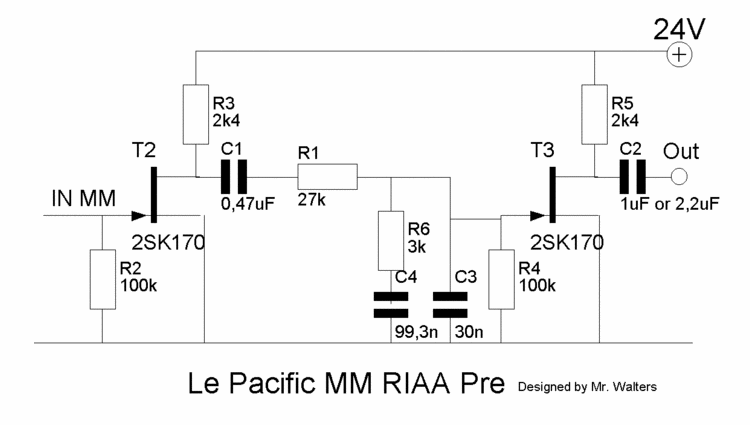
This document describes a DIY build of the Boozhound Laboratories JFET Phono Preamplifier constructed on a stripboard. The BHL preamp is primarily based on the Le Pacific RIAA phono preamplifier circuit. The construction utilizes brown polypropylene capacitors sourced from...
Nowadays, audio signal preamplifiers are utilized in numerous electronic devices. There are various types of audio preamp circuits, ranging from simple to complex designs. This document presents an effective design of a compact signal preamplifier circuit, which is ideal...
This circuit was submitted by Graham Maynard from Newtownabbey, Northern Ireland. It has an exceptionally good high frequency response, as demonstrated by applying a 100kHz squarewave to the input. Response graphs were produced using Tina Pro to highlight these...

The preamplifier circuit is designed to offer appropriate loading for phono cartridges with reluctance. It achieves a gain of approximately 25 dB at 1 kHz (converting an input of 2.2 mV to an output of 100 mV). The circuit...
This is a design for a low noise microphone preamplifier, which is ideally suited to low impedance (600 Ohm nominal) microphones. One limitation is that it is not balanced, which is not a problem in a home recording environment,...
Microphone amplifier schematics that can be utilized with either Electret Condenser Microphone (ECM) inserts or dynamic inserts, constructed with discrete components. The process of creating a PCB is straightforward. Begin by using PCB design software such as Eagle to...
Warning: include(partials/cookie-banner.php): Failed to open stream: Permission denied in /var/www/html/nextgr/view-circuit.php on line 713
Warning: include(): Failed opening 'partials/cookie-banner.php' for inclusion (include_path='.:/usr/share/php') in /var/www/html/nextgr/view-circuit.php on line 713