
ecm mic preamplifier
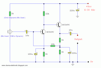
The microphone amplifier circuit is designed to amplify audio signals captured from either Electret Condenser Microphones (ECM) or dynamic microphones. The circuit typically includes a preamplifier stage, which is crucial for boosting the low-level signals generated by the microphones to a usable level for further processing.
The schematic may incorporate a transistor or operational amplifier as the main amplification component. In the case of an ECM, a biasing resistor is required to provide the necessary voltage for the microphone to operate. The output of the amplifier can be configured to drive further audio processing stages, such as filters or mixers, depending on the application.
The PCB design process involves several key steps. After creating the schematic using software like Eagle, the layout must be carefully designed to ensure minimal noise interference and optimal signal integrity. The traces should be wide enough to handle the current, and the placement of components should minimize the length of connections to reduce parasitic capacitance and inductance.
Once the design is finalized, printing on glossy paper allows for a clean transfer of the design onto the PCB. The use of a laser printer is recommended for its ability to produce a high-resolution image that adheres well during the heat transfer process. After adhering the design to the PCB, the heat application requires careful control to ensure that the ink transfers without damaging the board.
Following the transfer, the PCB is subjected to an etching process, typically using ferric chloride or a similar etching solution. This process removes the unprotected copper, leaving behind the desired circuit traces. After etching, the remaining ink can be removed, and the board can be drilled for component leads.
Finally, the components can be soldered onto the PCB, ensuring proper orientation and connection. The completed microphone amplifier circuit can then be tested for functionality, ensuring that it meets the desired specifications for audio amplification and quality.Microphone amplifier schematics that may be used with either Electret Condenser Microphone (ECM) inserts or dynamic inserts, made with discrete components : Make a PCB in very easy steps. ! Create your PCB design using PCB designer software like Eagle, print out your design on photo paper or glossy paper with laserjet printer.
Stick the prin ted design on the PCB (copper side) and then heat it using hot iron plate. The ink will stick on the PCB and it will be ready for etching process. Note: If you don`t have laserjet printer, then you can print the design on standard paper. Copy the printed design at Copy Service around your location (with glossy paper). 🔗 External reference
Related Circuits
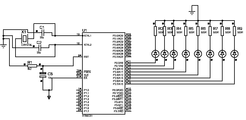
The first "Hello World!" project preferred for microcontrollers is LED blinking. An ATMEL 89C51 (40-pins DIP) microcontroller, based on the 8051 architecture, is used, which is ideal for first-time learning of MCU chips. The program is very simple and...

A general-purpose preamplifier/mixer accepts up to four inputs, has a gain of 1600, and provides bass and treble controls that can be varied ± 10 dB at 100 Hz and 10 kHz respectively. More: IC1 and IC2 = LM301A. This...
Build a large dancing robot. This was intended to be a walking robot, but it ended up moving in a more rhythmic manner. A video is available in the last step. The project involves the construction of a large dancing...
The artwork style of the operational amplifier and the meter face suggests that it is an ACC design from an old issue of ACC Notes. The second image was scanned, and the text below was written from scratch. If...

The microcontroller design features the microcontroller (MCU) in hibernation mode, which can only be awakened by a pulse (high-low-high) signal on the reset pin (active low). An accelerometer or an external real-time clock (RTC) serves as the wake-up source....
If you've crossed the line and play guitar or bass and also sing in a band, you're almost certain to have run into the situation that you step away from the mike to do a solo (or one of...
Warning: include(partials/cookie-banner.php): Failed to open stream: Permission denied in /var/www/html/nextgr/view-circuit.php on line 713
Warning: include(): Failed opening 'partials/cookie-banner.php' for inclusion (include_path='.:/usr/share/php') in /var/www/html/nextgr/view-circuit.php on line 713