
The simplest Metal detector with one BC548
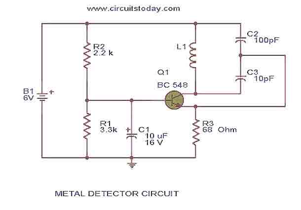
The circuit described is a simple yet effective metal detector that utilizes a Colpitts oscillator configuration. The core component of this design is a single transistor, which serves as the active element for generating oscillations. The oscillator operates at medium band frequencies, which are typically around the AM radio frequency range. The circuit is designed to work in conjunction with an old pocket radio, which acts as a receiver for the oscillations produced by the metal detector circuit.
In the initial setup, the radio is tuned to a specific frequency where it does not produce any sound, indicating that it is in resonance with the oscillator circuit. The proximity of the metal detector circuit to a metal object alters the inductance of the coil (L1), which is constructed by winding 60 turns of 36 SWG enameled copper wire around a 1 cm PVC tube. This change in inductance leads to a shift in the frequency of the oscillations generated by the Colpitts oscillator. As a result, the frequency of the metal detector circuit diverges from that of the radio, creating a situation where the two frequencies no longer cancel each other out. This results in the radio producing a hissing sound, which serves as an audible indication that metal has been detected.
It is important to note that powering the circuit with an adapter may introduce unwanted noise, which can interfere with the detection capabilities of the metal detector. Therefore, it is advisable to use a battery as the power source for this project, as it provides a cleaner power supply that enhances the performance of the radio and the metal detector circuit. Overall, this design represents an accessible and practical approach to metal detection, leveraging basic electronic principles and readily available components.This is the circuit diagram of a low cost metal detector using a single transistor circuit and an old pocket radio..This is nothing but a Colpitts oscillator working in the medium band frequency and a radio tuned to the same frequency.First the radio and the circuit are placed close.Then the radio is tuned so that there is no sound from radio.In this condition the radio and the circuit will be in same frequency and same frequencies beat off to produce no sound. This is the set up.When the metal detector circuit is placed near to a metal object the inductance of its coil changes , and so do the frequency of oscillations.Now the two frequency will be different , there will be no canceling and radio produces a hissing sound.The metal is detected. To make L1 make 60 turns of 36SWG enameled Copper wire on a 1 cm PVC tube. Powering the circuit using a adapter rather than a battery induces noise. It is always good to power radio projects from battery. 🔗 External reference
Related Circuits
The circuit indicates that the phone is in use by illuminating a red LED. When the phone is not in use, a green LED lights up. It operates without requiring external power and can be connected at any point...
The circuit was constructed using a few components powered by a 9 V battery for sensing the presence of bugs transmitting within the frequency modulation range. Frequency Modulation (FM) transmits its signal or information over a carrier wave by...
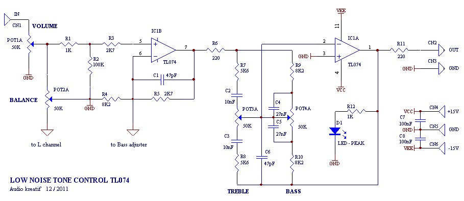
A tone control or pre-amplifier is an amplifier circuit that enhances audio signals. It is important to understand the characteristics, advantages, and disadvantages of various amplifier equipment, as the performance of different amplifiers may not show significant differences. The...
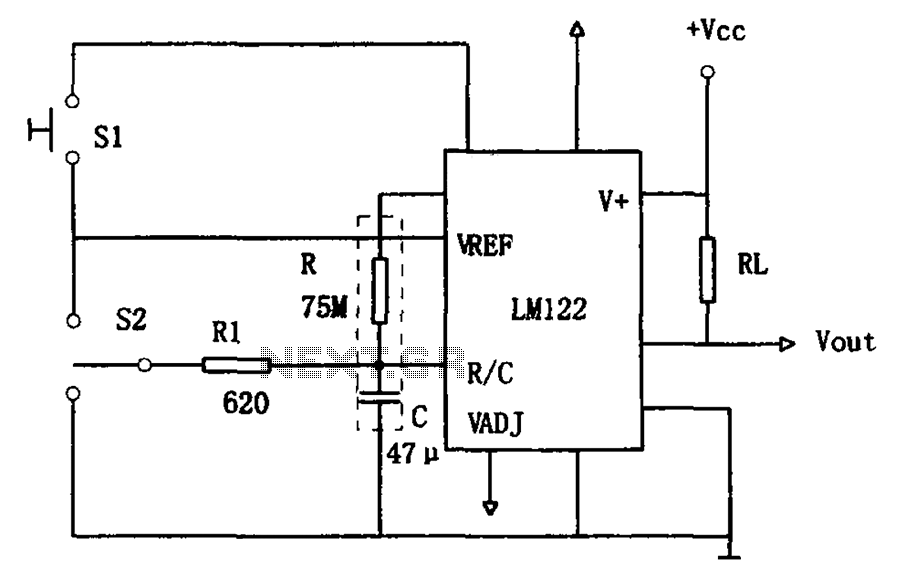
The circuit utilizes an LM122 timer, as illustrated in Figure 1, to manage various timing operations, including starting, resetting, and halting the process midway through. The operation of the circuit is governed by switching mechanisms. Switch S1 initiates the...
Join the forum discussion on this post. This is a simple home telephone ringtone generator circuit built using only a few electronic components. It generates a simulated telephone ringtone and requires only a DC supply. The home telephone ringtone generator...
During a telephone conversation with a distant subscriber, it is common to experience frustration due to the faintness of the voice, making it difficult to understand. To address this issue, a circuit for an inexpensive amplifier is presented. This...