
Tone control low noise circuit Schematic Diagram

In this tone control circuit, the design focuses on minimizing noise while maintaining sound quality. The use of specific components, such as the chosen op-amps and resistors, is critical to achieving the desired audio characteristics. The circuit architecture allows for flexibility in tuning the audio output, accommodating user preferences for treble and bass adjustments. The inclusion of both high pass and low pass filters ensures that the audio signal is processed effectively, allowing for a balanced output that enhances the listening experience. The careful selection of component values plays a significant role in determining the overall performance of the circuit, particularly in terms of noise reduction and signal integrity. The visual indicators, such as the LED, provide essential feedback to the user regarding the amplifier's operational status, ensuring optimal performance during use. This circuit is suitable for various audio applications, including home audio systems and professional sound equipment, where precise control over sound quality is paramount.Tone control or pre-amplifier is an amplifier circuit supporters. Sometimes some of us do not know where a good amplifier, a raft alone and the results are not much different or even the same. Therefore we must know the character of the advantages and disadvantages of each amplifier equipment.
Tone control low noise here does not mean without nois e, but noise compared with the lowest tone control on the market, for example Ronica transistor 4, TL-084, TC-2 LM833 etc. Potensio 1 serves to regulate the intensity / level of the incoming signal is assisted potensio 2 as balance / counterbalance.
Potensio 2 is still installed and is usually an optional component. 1-2uF/250V capacitor R1 is actually a brand name, but I prefer to replace it with a 1K resistor / 5% normal for reasons to avoid hum and interference sensitive. R2 R3 while minimizing interruption to adjust the impedance OP-amp 1. R4 and R5 serves to increase the gain of 1. 3 times. Pre amplifiers typically use a strengthening standards by 2 times, but by most of us think it has a noise.
So I chose the value of 1. 3 times, but the most minimal noise signal from the volume is enough to make the lamp light peak. For low noise. Cause of noise in op amp 1, apex audio even eliminate this stage. Can This step is also used as a buffer (jumper R5), the strengthening of a time. Lower values increase the value of R5 or R4 with consequent gains to be less, but remains at a value above 1 times due to input non-inverting path to take, so that the signal and noise can be reduced. R4 can also be replaced with a 10K trimpot and middle leg into the bass range adjuster (bass resonance).
C1 and C6 as a filter to reduce the treble / high frequency of excessive or often called oscillation prevention. R6 is actually an optional component of the impedance a little help customize the system. Ideally the same as the R8 R7 to facilitate give the sign of the gain on potensio panel tone control.
C2 and C3 form a series circuit treble filter (high pass filter), its value is greater then the sound that passed the mid. C4 and C5 assisted by R9 and R10 form the low pass filter (filter bass), the greater the value of C is a bass sound that will be missed the soft / low (maximum of 47nF), the smaller the value of c is the bass signal that is passed will further dip (dig-dig, c4 = c5 = 22nF).
This value is suitable for 27-33nF, 47nF instead (depending on taste). Pot 3 & 4 pot set treble and bass levels, the greater the greater the value of this potensio gains (bass & treble including potensio volume). R11 adjusts the output impedance, while the R12 and the red LED indicator that shows if the amplifier Peak has been given a full signal.
You are reading the Circuits of Tone control low noise circuit And this circuit permalink url it is 🔗 External reference
Related Circuits

This is a simple water level alarm circuit made using a 555 timer IC. The circuit will produce an alarm when the water level reaches a preset level. The water level alarm circuit utilizing a 555 timer IC is designed...
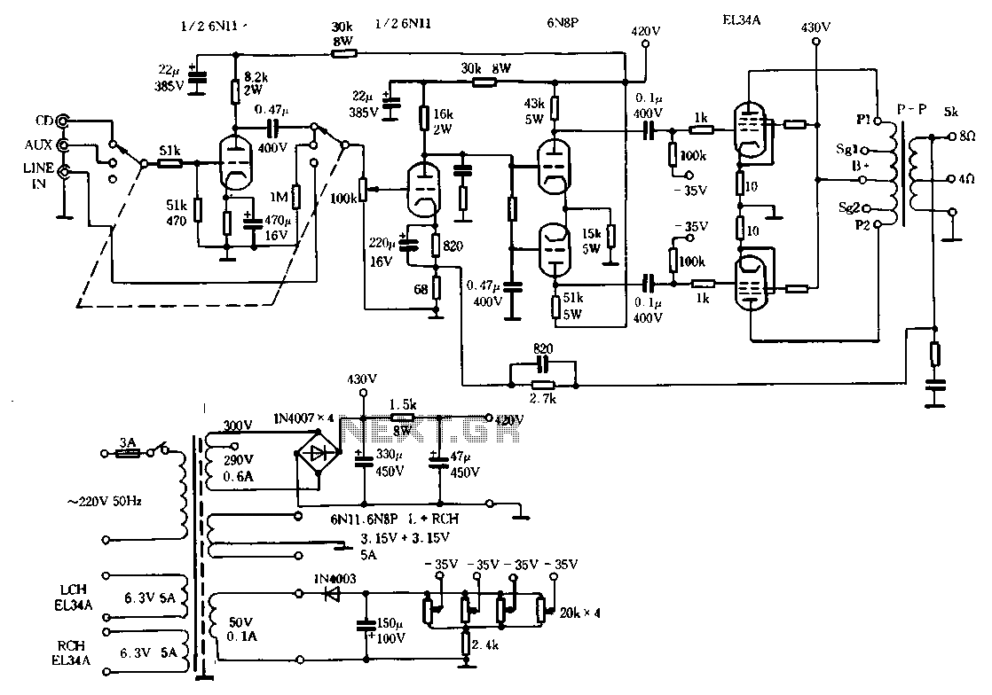
The Ml00 circuit is a typical tube circuit, functioning as a preamplifier. Its input stage utilizes a common cathode amplifier, followed by an inverter stage, culminating in a power amplifier that has been enhanced from a standard connection. This...
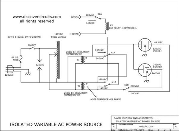
Variable AC Power Supply Circuit. In electronics, it is often useful to have a fully isolated variable AC power supply. With such a device, one can safely test various AC-powered circuits. A variable AC power supply circuit is an essential...
This is a transistor tester integrated into a circuit or printed circuit board (PCB). It is utilized when a project does not function correctly, allowing for the testing of electronic components. The transistor tester is a crucial tool in electronic...
The circuit was taken from an old Elektor electronics magazine and is a compact design suitable for generating high-intensity lighting effects during festivals, parties, and gatherings. Diodes D1 and D2, along with capacitors C1 and C2, form a voltage...
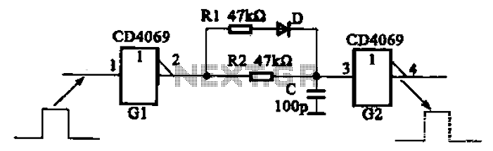
The inverter circuit using CD4069 is configured with a delay and width adjustment. When the output of the inverter (G1) is high, the capacitor (C) charges through resistor (R1) and diode (D). The voltage across capacitor C quickly reaches...