
Thermocouple cold junction compensator AD596 597 a circuit diagram of Temperature Monitor
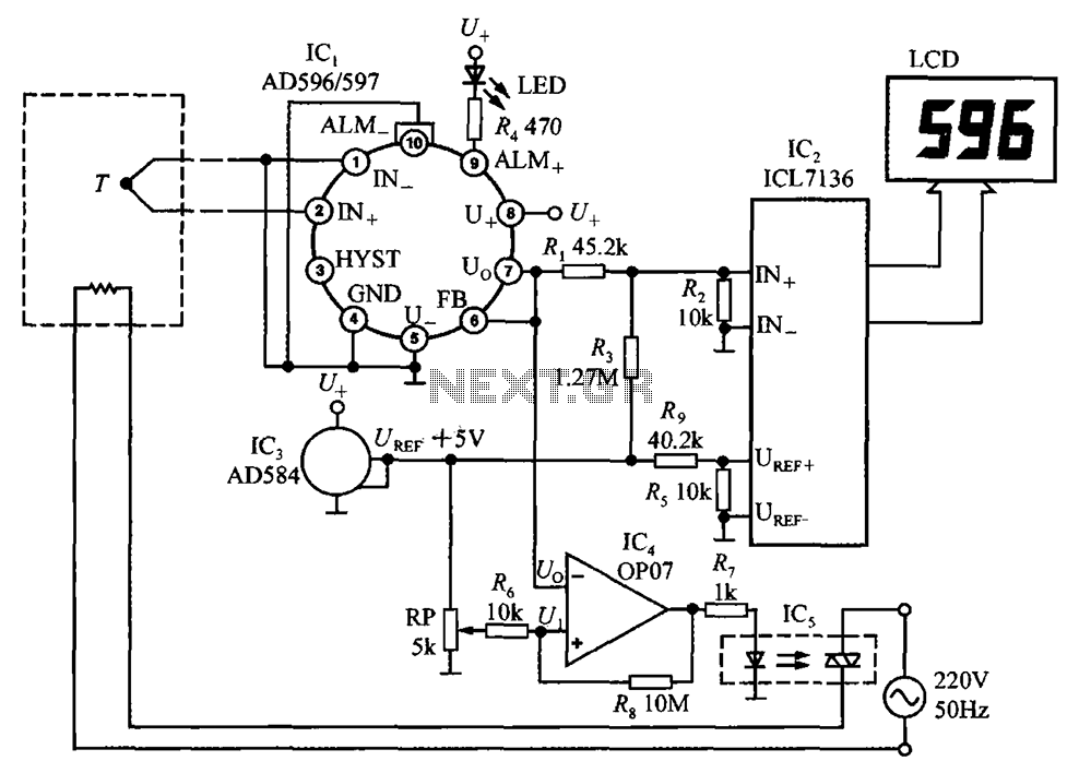
The circuit is designed for precise temperature control and monitoring, making it suitable for various applications where temperature regulation is critical. The use of the AD596/597 as a thermocouple signal conditioner ensures accurate readings from thermocouples, which are widely used for temperature measurement due to their wide temperature range and durability. The ICL7136 provides a reliable means of converting the analog signal into a digital format for easy reading on the LCD display. The inclusion of the OP07 operational amplifier enhances the circuit's ability to process signals accurately, ensuring that the temperature control mechanism responds appropriately to changes in temperature. The use of an optocoupler for controlling the triac adds an extra layer of safety and isolation, protecting the low-voltage components from high-voltage circuits. Overall, this temperature measurement and control instrument is a robust solution for maintaining desired temperature levels in various environments. Circuit from the AD596/597 form a temperature measurement and control instrument is shown in Fig. Here, AD596/597 (IC1) as a closed-loop thermocouple signal conditioner use. IC 2 is a monolithic CMOS 3 1/2 bit A/D converter ICL7136, can also be used to replace ICL7106, but power consumption will increase more. IC3 is + 5V bandgap reference voltage source AD584, + 5V reference voltage after R4, R5 partial pressure ICL7136 to provide a reference voltage of 1.000V, composed by the ICL7136 and LCD display for 2V full scale digital panel meter (DPM).
IC4 selects OP07 operational amplifier. RP is the set point adjustment potentiometer for setting the temperature to be controlled T1. Optocoupler IC5 with triac (TRIAC) is.The instrument has a temperature, temperature control, and open thermocouple failure alarm. AD596/597 output voltage by R1, R2 divider to the ICL7136 after the analog input IN +, IN-. Take R1 45.2k, R2 10k, the instrument display Fahrenheit (oF). Appropriately adjusted R1, the resistance value of R2 can also display in degrees Celsius. AD584 output + 5V reference voltage UREF, after RP, R6 partial pressure to obtain the reference voltage U1, then OP07-inverting input terminal, an inverting input termination Uo.
When Uo u1 when, op07 output high, by optical coupler electric heater 220v ac power supply is turned on, the to heat up. when t t1 uo u1, of becomes low, turn off power, forcing it lower temperature. ultimately climate control. open thermocouple, led emits light. if negative thermocouple ungrounded, once open-circuit fault meter will overload.
Related Circuits
The PCA84C-440/441 is a single-chip microcomputer integrated circuit produced by Philips. It is widely utilized in both domestic and imported large screen color televisions, including those manufactured by Philips and other brands. The PCA84C-440/441 IC is housed in a...
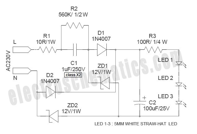
White Light Emitting Diodes (LEDs) now available can serve as a strong alternative to incandescent lamps in lighting applications. Today's White LEDs are... White Light Emitting Diodes (LEDs) represent a significant advancement in lighting technology, offering energy efficiency, longevity, and...
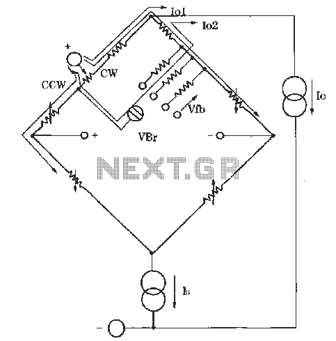
The circuit for zero and span adjustment consists of a feedback resistor network and a differential pressure sensing bridge measuring circuit. A constant current source, IO, represents the output current. The resistances of the four bridge arms are R1S,...
The original coil that came with the Heathkit project was preassembled at the factory. It had a diameter of around 15 cm (6 inches). A larger (30 cm, 12 inches) coil can be made using the following data. The design...
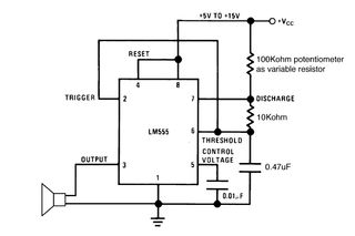
Setting the 555 timer in astable mode results in a continuous series of output pulses. The 555 timer IC, when configured in astable mode, operates as an oscillator, generating a square wave output. This configuration does not require any...
A truly timeless circuit. The LM317 is a versatile and highly efficient 1.2-37V voltage regulator that can provide up to 1.5A of current with a large heat sink. It is ideal for just about any application. This was the...