
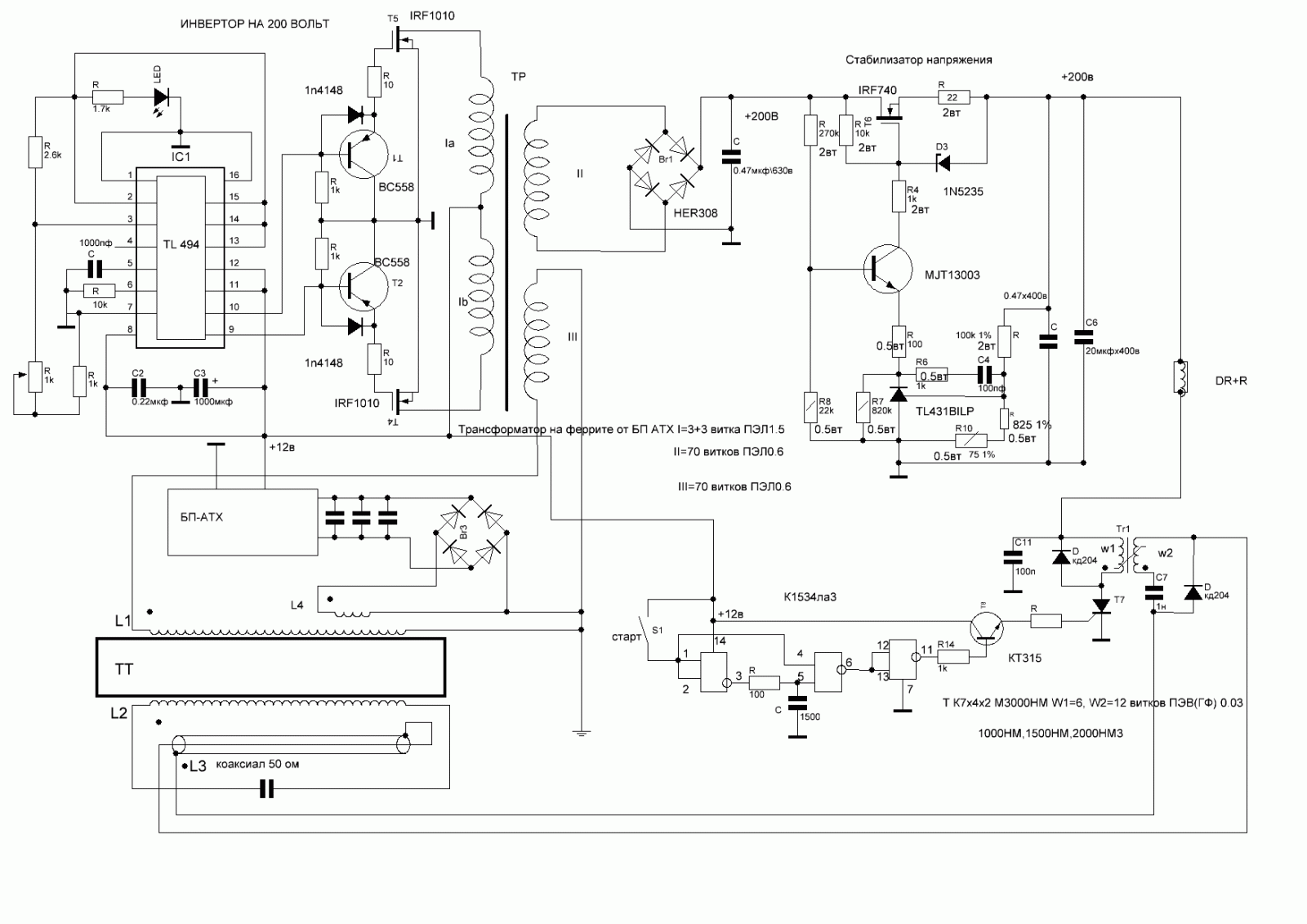
Heathkit Groundtrack GR-1290 metal detector schematic diagram
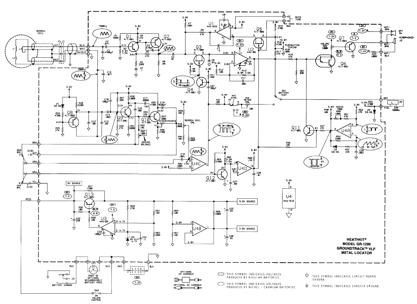
The design of a larger coil, specifically one with a diameter of 30 cm (12 inches), requires careful consideration of various parameters to ensure optimal performance. The coil's dimensions directly influence its inductance, resistance, and overall efficiency in an electrical circuit.
To construct a 30 cm coil, the wire gauge must be selected based on the intended current capacity and the coil's resistance. A thicker wire will reduce resistance but may increase the weight and cost of the coil. The number of turns is another critical factor; increasing the number of turns can enhance the inductance but may require more space and careful winding techniques to maintain uniformity and prevent overlapping.
The coil's core material also plays a significant role in its performance. A ferromagnetic core can significantly increase the inductance compared to an air core, but it also introduces losses due to hysteresis and eddy currents. If a ferromagnetic core is used, the type of material and its permeability must be chosen based on the frequency of operation and the desired inductance.
Additionally, the coil's layout should be designed to minimize parasitic capacitance and inductance. This can be achieved by maintaining proper spacing between turns and using appropriate insulation materials.
In summary, constructing a larger coil involves careful planning regarding wire gauge, number of turns, core material, and layout to achieve the desired electrical characteristics while ensuring efficiency and reliability in the overall circuit design.The original coil that came with the Heathkit project was preassembled at the factory. It had a diameter of around 15cm (6 inch). A larger (30cm, 12inch) coil can be made using the following data: 🔗 External reference
Related Circuits
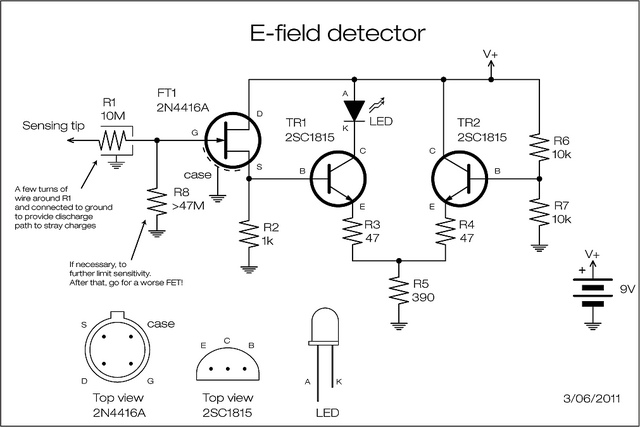
A JFET is employed to detect the electric field generated by high voltage power lines. The JFET amplifies the signal minimally but reduces the impedance and supplies current at a level appropriate for transistor amplification. The two transistors can...
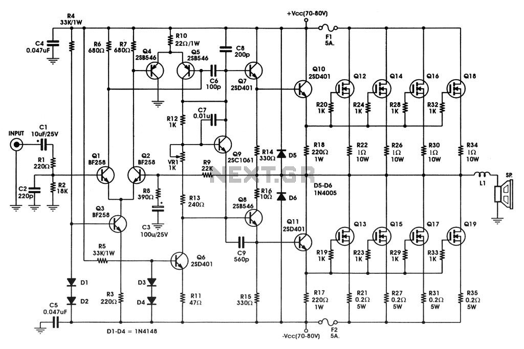
400 W MOSFET Audio Amplifier circuit using IRFP448. This circuit is categorized under amplifiers and includes five circuit diagrams. For more detailed information, refer to the main post titled "400 W MOSFET Audio Amplifier Using IRFP448." This post also...
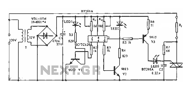
The circuit utilizes a built-in temperature sensor to control the triac TC620 for temperature regulation. The adjustment circuit consists of resistors Rp1 and Rn, which can be modified to set both the lower and upper temperature limits. LED1 illuminates...
Renewable energy discussions encompass various alternative energy, renewable energy, and free energy technologies. Discussions about environmental issues, global warming, and other related topics are also welcome. It is important to address the validity, organization, and general advice concerning the...
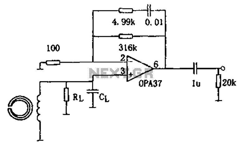
The circuit is a 90s common recorder head amplifier circuit that utilizes the ultra-low noise precision operational amplifier OPA37 as a preamplifier. This circuit is capable of providing standard NAB equalization. At a frequency of 1 kHz, it achieves...
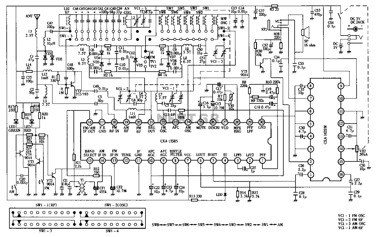
Desheng Rl212A 12-band FM, MW, SW, television sound stereo radio circuit diagram as follows: The Desheng Rl212A is a versatile radio circuit designed to operate across 12 different frequency bands, including FM (Frequency Modulation), MW (Medium Wave), and SW...