
Three Hour Timer
The circuit described operates as a battery charging timer and overcharge protection system for cordless drill batteries. It is crucial for maintaining battery health and longevity by ensuring that the battery does not remain connected to the charger beyond the recommended time. The relay Re1 serves as a switching mechanism that disconnects the battery from the charging circuit once the designated charging time has elapsed.
The charging time is indicated by ten LEDs, each representing a 20-minute interval. This visual feedback allows users to monitor the charging process easily. The timer is reset with each power application, ensuring that it is ready for a new charging cycle without manual intervention. The timing mechanism relies on an integrated circuit (IC3), which is reset by the combination of capacitor C4 and resistor R5, establishing a reliable timing function.
When the pre-set charging time is reached, the transistor Q9 is activated, which in turn energizes relay Re1, interrupting the flow of current to the battery. The connection of Q9 to the active-low EN input ensures that the counter remains in a stable state, preventing accidental reactivation of the charging current. The adjustable potentiometer P1 allows for customization of the charging time, accommodating different battery specifications and user preferences. The range of adjustment from 2 hours 15 minutes to 4 hours 30 minutes provides flexibility, while the specific setting of 30 kΩ for P1 offers a practical solution for standard charging needs.
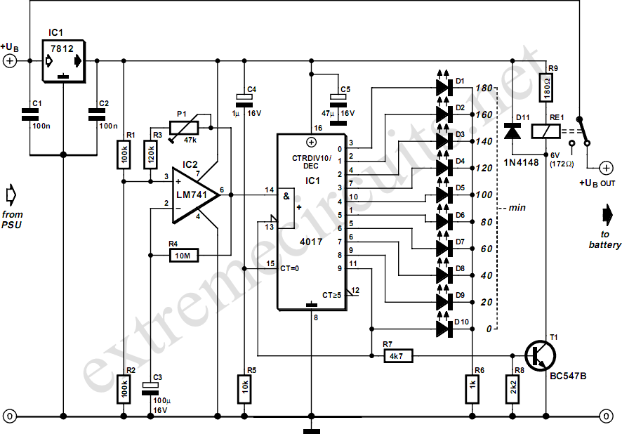
The timing accuracy is deemed adequate for this application, although it is acknowledged that the first clock cycle may be longer due to the initial charging of capacitor C3. This characteristic is an important consideration during the design phase, as it affects the overall timing behavior of the circuit. The circuit's design effectively addresses the need for a reliable and safe battery charging solution, ensuring that users can charge their cordless drill batteries without the risk of overcharging.Manufacturers of cordless drills generally recommend a battery charging time of three hours. Once the charging time is up the battery must be disconnected from the charger: if you forget to do this there is a danger of overcharging the battery. This circuit, which sits between the charger circuit and its battery socket, prevents that possibility:
the contact of relay Re1 interrupts the charging current when the three hours are up. Ten LEDs show the remaining charging time in steps of 20 minutes. The timer is reset each time power is applied and it is then ready for a new cycle. When power is applied IC3 is reset via C4 and R5. When the charging time has elapsed, Q9 (pin 11) goes high, which turns the relay on and interrupts the charging current. Since Q9 is connected to the active-low EN (enable) input, the counter will now remain in this state.
The charging time can be adjusted from about 2 hours 15 minutes to 4 hours 30 minutes using P1. The author set P1 to 30 k, giving a charging time of 3 hours 7minutes. The greater the resistance of P1, the shorter the charging time. The timing of the circuit is not particularly precise, but its accuracy is entirely adequate for the job. When adjusting the charging time it is worth noting that therst clock cycle after the circuit is turned on (from Q0 to Q1) is longer than the subsequent ones.
This is because initially capacitor C3 has to be charged to around half the supply voltage. 🔗 External reference
Related Circuits
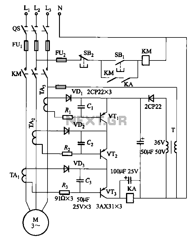
Drawing transistors that comprise the gate VTi, VT2, VT3, and similar components. The schematic involves a configuration of transistors designated as VTi, VT2, and VT3, which are integral to forming a gate structure. These transistors are typically arranged in a...
Figure 1 illustrates an enhanced trigger timing circuit that utilizes two Programmable Unijunction Transistors (PUTs). When a set signal is applied, the circuit is activated, causing transistor VT1 to enter the conduction state and energizing relay K. This action...
This device is a simple timer, allowing to keep on the headlights of your vehicle for about 1min. and 30sec., e.g. when accessing some dark place, without the necessity of coming back to switch-off the lights. The circuit design for...
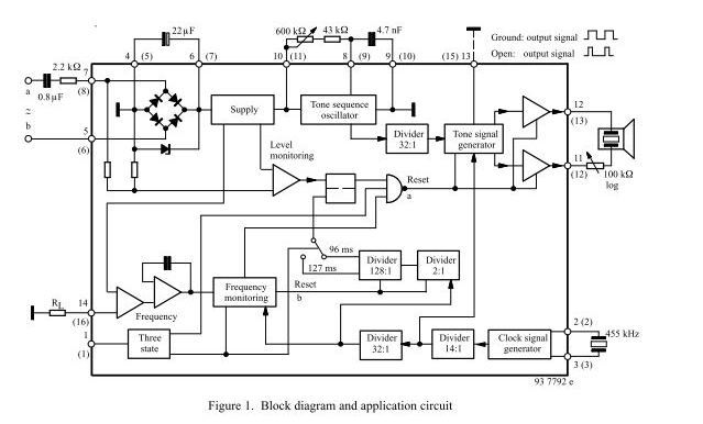
The three-tone ringing integrated circuit U4076B, in conjunction with a piezo transducer or loudspeaker, replaces the normal electromechanical telephone bell. It is operated with the ringing current frequency. The U4076B integrated circuit is designed to generate a three-tone ringing signal,...
Speaker relay delay controlling circuit for audio amplifier The speaker relay delay control circuit is designed to protect audio amplifiers and speakers from potential damage caused by inrush current or transient signals during power-up or power-down sequences. This circuit typically...
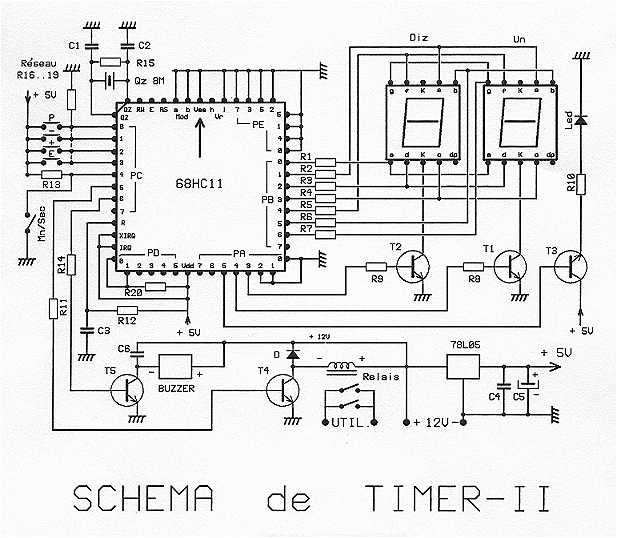
The timer is proposed an effective model for controlling an external load 8A/380V. Equipped with a 68HC11 mu.P associated with an 8 MHz crystal, it can get very precise programmable durations. Two lines are planned: from 0 to 99...