
three rails regulated power supply
This circuit design effectively demonstrates the principles of voltage regulation and power supply design, making it suitable for various applications in electronics. The use of diodes for rectification ensures that the AC input is converted to a usable DC output, while capacitors serve to smooth out the voltage fluctuations, providing a stable output. The inclusion of the 7805 voltage regulator allows for precise regulation of the +5V output, which is critical for powering sensitive digital circuits. The thyristor and Zener diode work together to protect the circuit from overvoltage conditions, ensuring the longevity and reliability of the power supply.
Furthermore, the adjustable power supply capability from 3V to 30V allows for versatility in powering different devices and circuits, catering to a wide range of electronic testing and prototyping needs. The current rating of up to 3A ensures that the power supply can handle moderate loads without overheating or failing. The audio-visual indicators for short circuit detection enhance user safety and facilitate troubleshooting during testing.
Overall, this circuit serves as a robust solution for providing stable, regulated power in laboratory environments, making it an invaluable tool for engineers and hobbyists alike. Its design simplicity, combined with essential protective features, underscores its effectiveness in various electronic applications.This circuit generates 3 source regulated voltages applying a minimum of electronic parts. The output DC voltage are +12V ; +5V and -5V. Diodes D2 and D3 conduct full-wave rectification, at the same time charging capacitor C2 on each halves of the alternating current cycle. At the same time, diode D1 with capacitor C1, and. This is the circuit di agram of 5V Regulated Power Supply circuit, featured with over voltage protection. The circuit is based regulator chip 7805; Thyristor SCR 2N1595 and Dioda Zener 1N3997 for overvoltage protection circuit. The 5V regulated power supply is apply 74LS series integrated circuits which has to be really precise and tolerant of voltage.
This is an adjustable and regulated power supply with 3V to 30V output voltage and supply up to 3A direct current. This circuit featured with short circuit protection and overload protection. Download the manual of this circuit include the schematic and part list HERE This is definitely an effective 4-output stage stabilized DC power supply unit for testing electronic circuits.
It delivers very well regulated and stabilised output, that is important for most electronic circuits to provide good results. The circuit gives you an audio-visual indication if there is a short circuit in the PCB under test, so the.
This is bench power supply circuit for multi purpose usage. This bench power supply features three solid-state DC power supplies. The first supply gives a +1. 5 to +15 volts at 1 ampere. The second supply gives a -1. 5 to -15 volts at 1 ampere. The third has a fixed 5V at 3 amperes. All DC. The above diagram is a basic Uninterupted Power Supply (UPS) circuit. This is a very simple and inexpensive circuit. This circuit can be adapted/modified for other regulated and unregulated voltages by using different regulators and batteries. For a 15 Volt regulated supply, you may apply two 12V batteries connected in series (it will become 24V).
🔗 External reference
Related Circuits
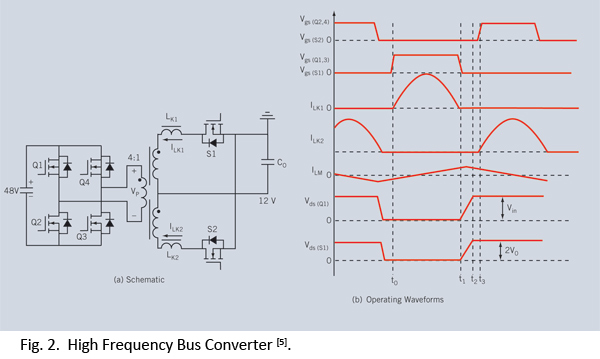
Distributed power systems are commonly used in telecommunications, networking, and high-end server applications, utilizing a 48 V bus voltage derived from the telecom industry. This 48 V bus supplies several isolated point-of-load (POL) converters that power the end loads,...
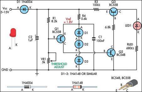
This is a simple low supply rail detection circuit that is inexpensive and can be assembled in approximately 20 minutes. Its low power consumption makes it suitable for integration into battery-powered devices. Instead of utilizing an operational amplifier, the...
Proposed power supply for amplifier 100W v-mosfet is what appears in the above form. It has separated supply for the various stages of supply, stage for power, stage for control, supply for preamplifier and for stage of protection. Whoever...
This chapter presents a variety of circuits for basic power supplies, including both line-powered and inverter types, some of which feature regulators, modulation inputs, and additional functionalities. Several circuits have been reverse-engineered from actual commercial products, and others, designed...
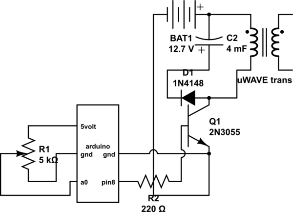
If both devices need to be powered from the battery, should the emitter be connected to the ground of the Arduino and the battery to prevent current from flowing through the Arduino ground, ensuring a clean pulse? Alternatively, can...
This page investigates a simple PA for 50MHz. This power amplifier will boost a low-level signal about 10-20mW to over 100mW. The power consumption will yet be quite low. At the bottom of this page, a complete transmitter based...
Warning: include(partials/cookie-banner.php): Failed to open stream: Permission denied in /var/www/html/nextgr/view-circuit.php on line 713
Warning: include(): Failed opening 'partials/cookie-banner.php' for inclusion (include_path='.:/usr/share/php') in /var/www/html/nextgr/view-circuit.php on line 713