
Low Supply Rail Detection
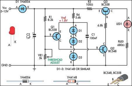
The low supply rail detection circuit operates effectively as a voltage monitoring system. The core functionality relies on three transistors (Q1, Q2, and Q3) configured in a way to amplify the detection of low voltage conditions. The circuit begins with the establishment of a voltage reference through diodes D1-D3, which provides a stable 1.8V reference voltage (Vref) for the emitter of Q1.
The voltage divider, composed of resistor R1 and variable resistor VR1, plays a critical role in determining the threshold voltage at which the circuit activates. When the input voltage drops below the reference voltage, Q1 is triggered, allowing current to flow to Q2. This current flow subsequently activates Q3, which drives LED1. The LED serves as an indicator of the circuit's operational state; its brightness varies inversely with the supply voltage.
The adjustment of trimpot VR1 allows for fine-tuning of the activation point of the LED, enabling the user to set a specific low-voltage threshold tailored to the application requirements. The circuit is designed to maintain low power consumption, with typical current draw being less than 2mA when the LED is off, ensuring that it is suitable for battery-operated devices.
For applications outside the 6-12V range, the resistance value of RLED can be calculated using the provided formula, allowing for adaptability in different voltage environments. This circuit design is particularly useful in scenarios where monitoring supply voltage is critical, providing a simple yet effective solution for low voltage detection.Here`s a simple low supply rail detection circuit that costs peanuts and takes just 20 minutes or so to make. Its power consumption is quite low, so it could easily be built into battery-powered devices. Instead of using an op amp, the circuit is built around three low-cost transistors (Q1-Q3). Diodes D1-D3 form a 1. 8V voltage reference (Vref) for the emitter of Q1. If the voltage across the voltage divider formed by R1 and VR1 is less than this, Q1 turns on and supplies Q2 with base bias current. This turns on Q3 in proportion to this bias current which then drives LED1. The brightness of the LED gives an indication of the severity of the low voltage condition. The brighter the LED, the lower the supply voltage. Trimpot VR1 is adjusted so that LED1 just comes on at the desired low-voltage point. The current consumption is typically less than 2mA when LED1 is off. Finally, the value shown for RLED is suitable for 6-12V operation. For other voltages, RLED can be calculated using the formula RLED = (Vcc - 1. 8)/0. 01 (this equates to a current of about 10mA). 🔗 External reference
Related Circuits
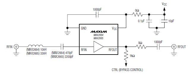
A simple, low-cost, and ultra-compact VHF/UHF low-noise amplifier circuit can be designed using the MAX2664 and MAX2665 ultra-compact LNAs for VHF/UHF applications. These devices incorporate a broadband LNA with an integrated bypass switch. The MAX2664 covers the UHF frequency...
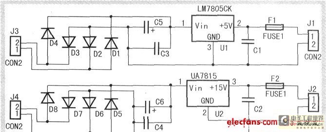
When the input voltage is between 198-242V, the average load current should be maintained at 0.5-1A, and the output voltage must remain at 15V with an error margin of less than 5%. The design and measurement of the stabilized...
The camera power supply circuit illustrates the essential power supply required for the proper functioning of the camera. This power supply circuit is composed of a stable voltage control integrated circuit. The camera power supply circuit is critical for ensuring...
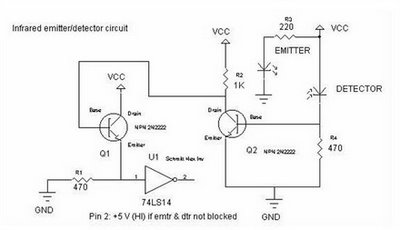
To achieve an optimal voltage swing, the resistance value of R1 must be selected with precision. The sensor resistance, Rsensor, equals a when there is no light exposure and b when light is present. The voltage difference between these...
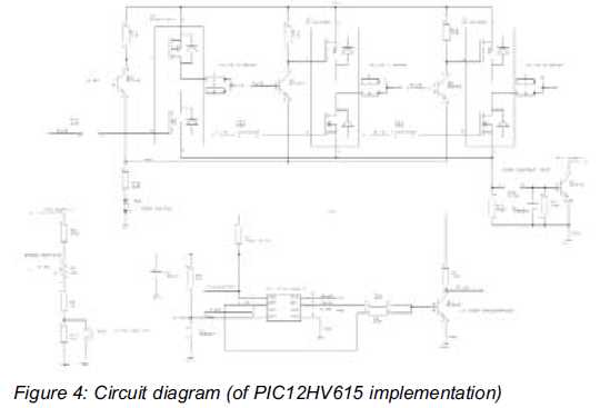
This article discusses a minimal resource microcontroller implementation for a three-phase Brushless DC (BLDC) motor, focusing on a closed-loop speed motor controller application based on a Microchip PIC12 device. It demonstrates how minimization techniques can reduce the number of...
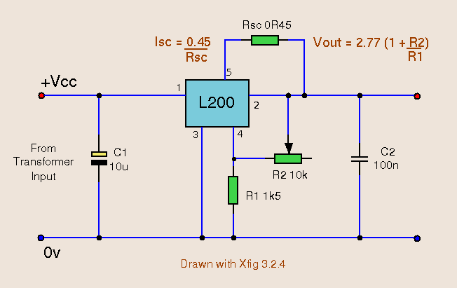
The versatile 5 pin L200C regulator offers both voltage and current regulation in a single package. The IC also features thermal shutdown and input over voltage protection up to 60 Vdc. The package is also available as L200CV which...