
Three-tone electronic doorbell 1
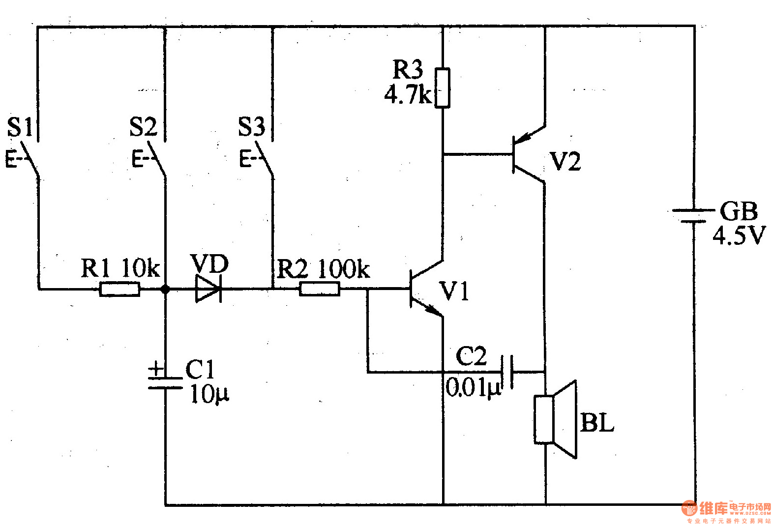
The three-tone electronic doorbell circuit is designed to produce distinct sound tones based on the button pressed. The circuit utilizes three buttons (S1, S2, S3) that, when activated, trigger different sound outputs through the speaker (BL). Each button corresponds to a specific tone, achieved by altering the circuit's configuration through the transistors (V1 and V2).
Transistor V1, which can be either a 3DG6 or S9013 silicon NPN type, is responsible for amplifying the signal generated when a button is pressed. Similarly, transistor V2, which can be a 3AX31 germanium PNP type, helps to manage the power supply to the speaker, ensuring that the sound output is both loud and clear.
The resistors (R1-R3) are critical for controlling current flow within the circuit, and their specifications as 1/4W carbon film or metal film types ensure reliability and stability during operation. Capacitor C1, rated for 16V, is an electrolytic capacitor that provides necessary filtering and stabilization, while C2, which can be a monolithic or polyester capacitor, aids in the timing and tone generation aspects of the circuit.
The diode (VD), which can be a 2AP9 germanium diode or a 1N4148 silicon switching diode, serves as a protective component, allowing current to flow in one direction and preventing potential damage to the circuit from reverse polarity.
Overall, this circuit is a practical application of basic electronic components, providing an engaging and functional doorbell solution with customizable sound options. Proper selection and integration of these components are essential for achieving the desired performance and longevity of the doorbell system.The three-tone electronic doorbell circuit consists of buttons Sl-S3, transistors Vl, V2, speaker BL, resistors Rl-R3, capacitors Cl, C2, diode VD and battery GB, and it is shown in Figure 3-109. Rl-R3 use the 1/4W carbon film resistors or metal film resistors. Cl uses the electrolytic capacitor with voltage in 16V; C2 uses the monolithic capacito rs or polyester capacitors. VD uses the 2AP9 germanium ordinary diode or 1N4148 silicon switching diode. Vl uses the 3DG6 or S9013 silicon NPN transistor; V2 uses the 3AX31 germanium PNP transistor. 🔗 External reference
Related Circuits
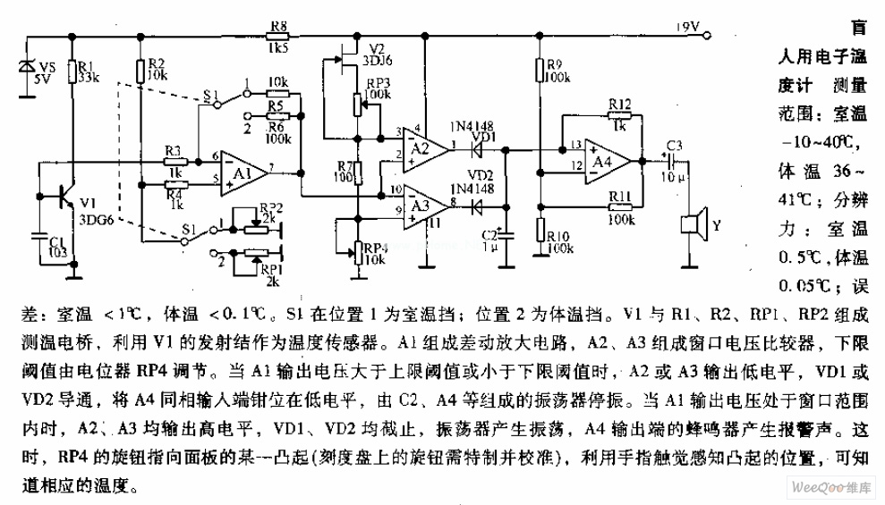
Measuring range: room temperature is -10 to 40 degrees Celsius; body temperature is 36 to 41 degrees Celsius; Resolution: room temperature is 0.5 degrees Celsius, body temperature is 0.05 degrees Celsius; error: room temperature <1 degree Celsius, body temperature <0.1 degrees Celsius. When switch S1 is in position 1, it displays the room temperature profile; position 2 displays the body temperature profile. Components V1, R1, R2, RP1, and RP2 form the temperature measurement circuit. The temperature measurement circuit is designed to monitor and display two distinct temperature ranges: ambient room temperature and body temperature. The circuit operates with a measuring range for room temperature from -10 to 40 degrees Celsius and for body temperature from 36 to 41 degrees Celsius. The resolution of the circuit is fine-tuned to provide accurate readings, with a room temperature resolution of 0.5 degrees Celsius and a body temperature resolution of 0.05 degrees Celsius. The specified error margins indicate a maximum deviation of less than 1 degree Celsius for room temperature measurements and less than 0.1 degrees Celsius for body temperature measurements. The circuit utilizes a switch, S1, which allows the user to select between the two temperature profiles. In position 1, the circuit outputs the room temperature, while in position 2, it outputs the body temperature. The operational components include a voltage source (V1), resistors (R1, R2), and potentiometers (RP1, RP2) that are integral to the measurement process. Resistors R1 and R2 are likely part of a voltage divider network that aids in scaling the temperature sensor output to a readable format. Potentiometers RP1 and RP2 can be used for calibration purposes, allowing fine adjustments to ensure that the readings are accurate within the specified error margins. The temperature sensor, which is not explicitly mentioned but is assumed to be part of the circuit, converts temperature changes into an electrical signal that can be processed by the circuit. The output from the sensor is conditioned by the resistive components to produce a voltage level that corresponds directly to the measured temperature. This voltage is then displayed on an appropriate display unit, which could be an analog gauge or a digital readout, depending on the design of the circuit. Overall, this temperature measurement circuit is a practical solution for monitoring both ambient and body temperatures with high accuracy and user-friendly operation through the selection switch.
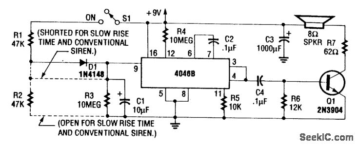
For a normal wailing tone, short D1 and leave R2 open. To achieve a fast rise and slow fall in frequency, include both D1 and R2. Utilizing a CD4046B with a diode-RC network as illustrated generates a siren tone...
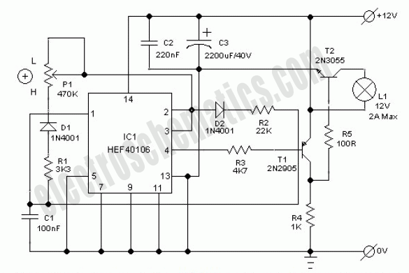
This electronic lighting dimmer circuit is designed to control the brightness of incandescent lamps, but it is not suitable for fluorescent lamps. It operates with both 110V and 220V AC power sources. The circuit is connected in series with...
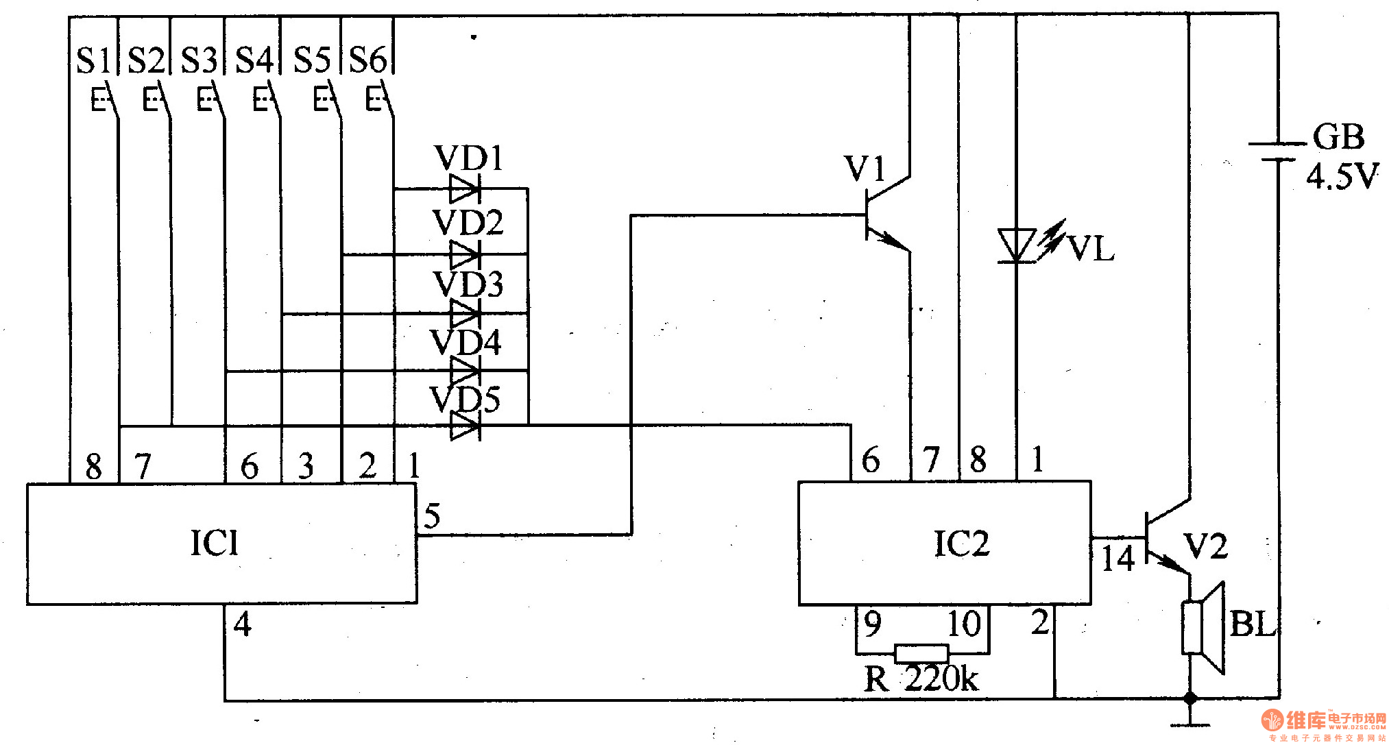
The electronic doorbell circuit utilizes a password mechanism and includes both an electronic password circuit and a music generation circuit, as illustrated in Figure 3-118. The electronic password circuit is comprised of integrated circuit IC1, keys S1-S6, and diodes...
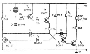
A simple and practical electronic bell circuit can be constructed using the provided schematic diagram. This circuit can function as a doorbell or an alarm system. It utilizes only a few transistors along with several common components. The circuit...
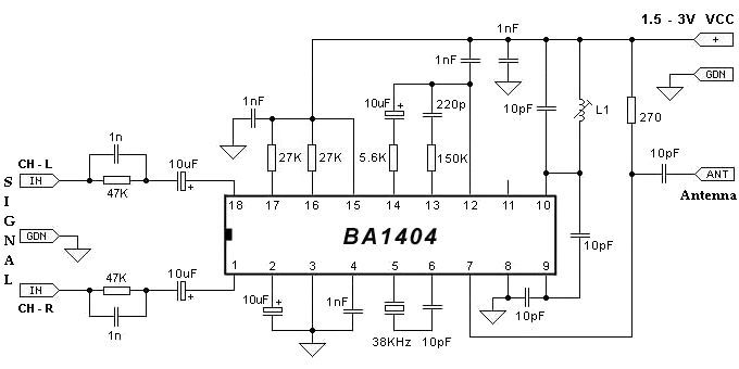
The BA1404 can be utilized to create a simple and effective FM stereo modulator electronic project. This BA1404 FM stereo modulator device operates within the FM broadcast band (75-108 MHz) and requires only a few common external components. The...