
ELECTRONIC SIREN
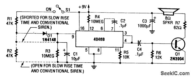
The circuit utilizes the CD4046B phase-locked loop (PLL) integrated circuit, which is adept at generating various frequency tones, including siren tones. The VCO within the CD4046B is key to producing the desired audio frequency output.
In the configuration for a normal wailing tone, the diode D1 is shorted, effectively bypassing it, while resistor R2 is left open. This configuration allows the VCO to operate at a steady frequency, resulting in a continuous wailing sound. The absence of R2 means that the timing capacitor associated with the VCO discharges quickly, contributing to the wailing effect.
To modify the circuit for a fast rise and slow fall frequency response, both D1 and R2 must be included in the circuit. The presence of R2 introduces a time constant that slows down the discharge of the timing capacitor, thereby creating a gradual decrease in frequency. This results in a siren tone that rises quickly and falls slowly, mimicking the sound of emergency vehicle sirens. The diode D1 in this configuration acts to shape the waveform produced by the VCO, ensuring that the frequency modulation occurs as intended.
The diode-RC network plays a crucial role in shaping the output waveform and controlling the frequency characteristics of the siren tone. By adjusting the values of R2 and the timing capacitor, the designer can fine-tune the rise and fall times of the frequency modulation, allowing for a versatile range of siren tones suitable for various applications.For normal wailing tone, short D1 and open R2. For fast rise and slow fall in frequency, include D1 and R2. Use of a CD4046B with a diode-RC network as shown produces a siren tone, using a VCO. 🔗 External reference
Related Circuits
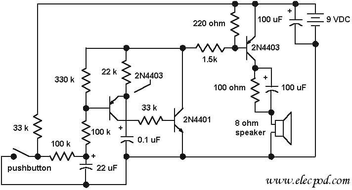
The core component of the circuit is a dual transistor flasher with frequency modulation applied to the base of the first transistor. When the pushbutton is pressed, the oscillation frequency increases to a peak, and when the button is...
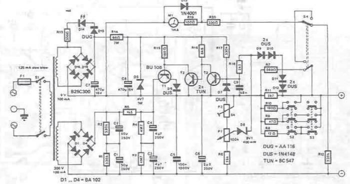
A DC power supply can be designed using high voltage transistors to provide an adjustable supply voltage ranging from 10 to 300 volts, which can be modified with potentiometer P1. Transformers used in these power supplies typically feature multiple...
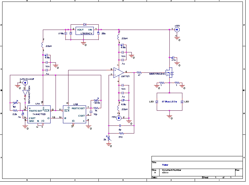
A Prototype Sample and Hold Circuit - The original concept for the veto front-end amplifiers was to continuously sample the input pulse height and maintain the pulse height for any pulses exceeding a low voltage threshold (approximately 10 mV)....
XP power plug, FU fuse, ST temperature control, T1 low-voltage transformers, S1, S2 door interlock switch, S3 threshold control switch, RT thermal sensor, K1, K2 relay, EL furnace light, M1 wheel motor, M2 fan motor, T2 high-voltage transformer, C...
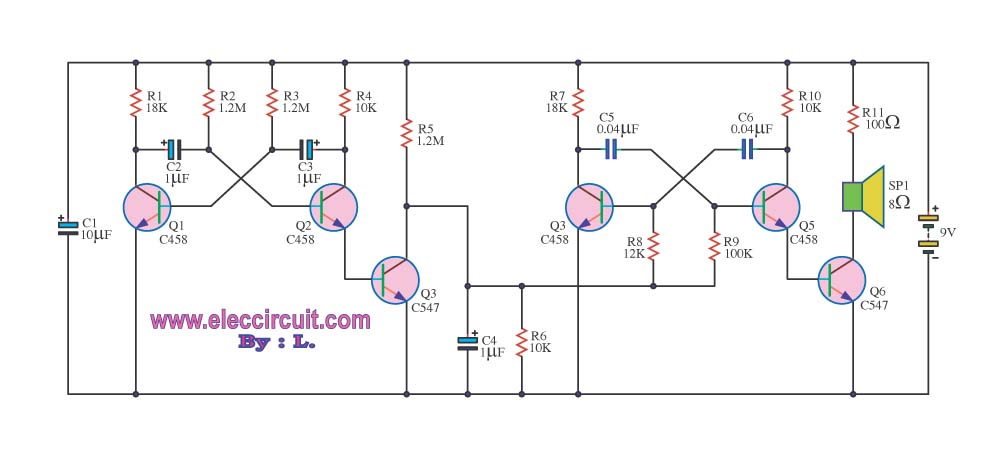
This circuit generates a sound similar to that of ambulance sirens. It differs from typical ambulance siren circuits in its design. The circuit utilizes a combination of oscillators and amplifiers to produce a sound that mimics the varying pitch and...
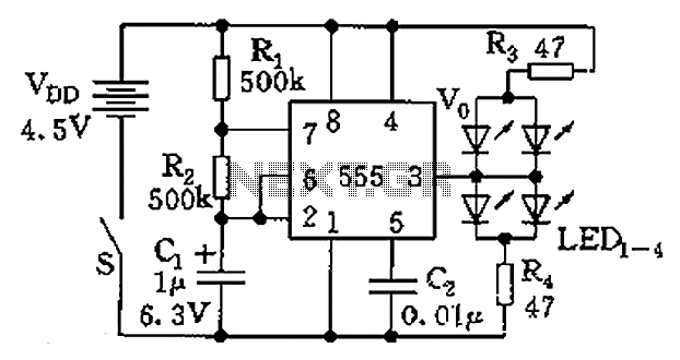
The circuit consists of a 555 timer and a light-emitting diode (LED) array. The 555 timer, along with resistors R1, R2, and capacitor C1, forms an astable multivibrator configuration. The oscillation frequency is calculated using the formula f =...