
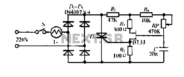
Thyristor / TRIAC Tester
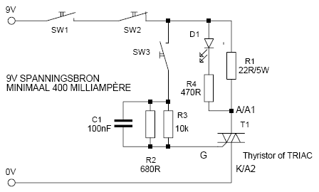
The thyristor TRIAC tester circuit is designed to assess the operational integrity of thyristors and TRIACs, utilizing a straightforward mechanism to indicate their functionality. The circuit operates with a supply voltage of 9V, requiring a minimum current of 400mA, which is ideally sourced from a laboratory power supply for precise control over the holding current. This ensures that the tester can adequately evaluate the components without the limitations associated with a standard 9V battery.
The core components of the circuit include three switches: SW1, SW2, and SW3. SW1 serves as the main power switch to turn the circuit on or off. SW2 is a normally closed pulse switch that, when activated, will cut off the current flow, causing the LED indicator (D1) to turn off if the tested component is functioning correctly. SW3 is a momentary switch that, when pressed, allows current to flow through the circuit, illuminating the LED if the component under test is operational.
Resistors R1, R2, R3, and R4 are strategically placed to limit current and set the appropriate biasing for the LED and the testing circuit. R1, rated at 22Ω and 5W, is critical for managing the power dissipation in the circuit, while R2 (680Ω), R3 (10kΩ), and R4 (470Ω) help to establish the necessary voltage levels for proper operation. Capacitor C1, valued at 100nF, serves to filter out any noise in the power supply, ensuring stable operation.
The tester also incorporates three Hirschmann measurement terminals, which provide a secure connection to the thyristor or TRIAC being tested. These terminals are essential for maintaining a solid connection during the testing process and are sourced from Conrad components (138487-12 or 138495-12).
Overall, this thyristor TRIAC tester circuit provides a reliable means for evaluating the performance of these semiconductor devices, ensuring that they can be tested effectively in a variety of applications.This is a simple but effective and thyristor TRIAC Tester. Operation at a good thyristor / triac: LED lights when SW3 is pressed. LED turns off when SW2 is pressed. If this occurs, the thyristor / triac OK. Tip: Hirschmann clips for the tested thyristor / triac connecting, including this quotation terminals. The supply voltage is 9V, with a minimum current of 400mA. Ideally, a labvoeding because it determines the holding current can be. Never use a 9V battery (6F22). SW1 = On / Off switch Conrad 701343-12 SW2 = pulse switch - normally closed Conrad 701114-12 SW3 = pulse switch - make Conrad 701113-12 R1 = 22? - 5W R2 = 680? R3 = 10k? R4 = 470? D1 = LED - red, 20mA C1 = 100nF T1 = To Test SCR / TRIAC 3 measurement terminals Hirschmann, Conrad 138487-12 or 138495-12
🔗 External reference
Related Circuits
This circuit utilizes the well-known and easily accessible LM3914 integrated circuit (IC). The IC is straightforward to operate, requiring no external voltage regulators due to its built-in voltage regulation capability, and can be powered by a variety of sources....
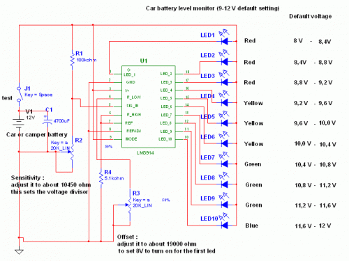
Camping today often requires bringing various electronic devices for daily activities or entertainment. Frequently, a charge is needed for these devices. In modern camping scenarios, the reliance on electronic devices has significantly increased. Campers typically bring smartphones, tablets, GPS devices,...
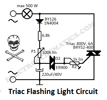
This flashing light circuit utilizes triacs to produce an intermittent light with variable frequency. Additional components include the D1 diode and a semi-adjustable resistor. The flashing light circuit is designed to create a visual indication through intermittent illumination, which can...
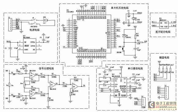
A one-chip computer has been utilized to design this survey meter, which directly displays the measured resistance on an LCD screen. The measurement range extends from 0 to 9999 kΩ, and the device can simultaneously store the measured data,...

A relay is an effective solution for switching a mains voltage circuit, particularly in applications where long switching times and high currents are present. However, a... A relay is an electromechanical switch that uses an electromagnetic coil to control the...
Electrical flow through the saddle j pounds. TV added in a controlled manner Qian Mountain amphipod species lI- ii mi pulsating chord electric. This electric again. The DC Bamboo Division I and the second voltage supply voltage step trigger...