
Tip a battery discharge control circuit
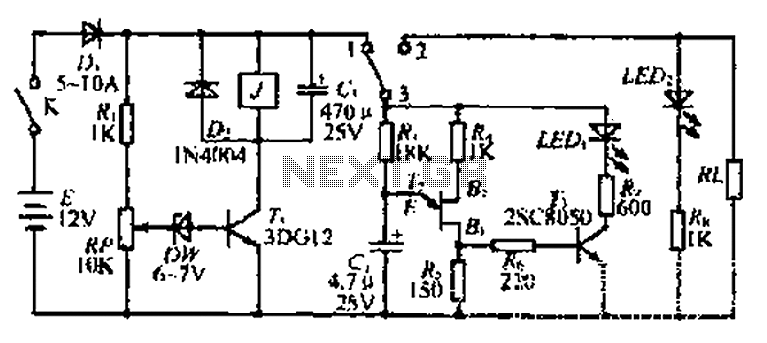
The circuit operates by monitoring the battery voltage continuously. When the voltage reaches a critical level, the relay, controlled by resistors that set the voltage thresholds, will activate. The normally open contact closes, allowing current to flow to the load, while simultaneously illuminating the green LED to indicate that the system is operational.
As the battery discharges and the voltage drops to around 10.5V, the control circuit will trigger the normally closed contact to open, cutting off power to the load. This action is crucial to prevent the battery from entering a deep discharge state, which can lead to irreversible damage. The flashing red LED serves as a visual cue to the user that the battery requires charging.
The time required for recharging the battery is influenced by the charge characteristics of the specific battery used in the circuit. A capacitor may be included to smooth out voltage fluctuations during the charging process, ensuring stable operation. The design of the circuit takes into account various parameters such as the charge time, the discharge rate, and the load requirements to optimize the performance and longevity of the battery.
In summary, this discharge control circuit is vital for maintaining battery health by preventing over-discharge, providing visual indicators for operational status, and ensuring safe charging practices. By R. RP, DW, f TV over the composition of the discharge control circuit: B, consisting of n Island and over-discharge circuit prompted the stage Ji pod K. Gracilaria battery v oltage by R., RP partial pressure breakdown DW flE f saturated conduction, following electrical JI. For. J. 3 normally open contact connected, the green LED light. Load electrical work. When the battery voltage drop Artemisia born when the original is not given JO ~ 10.5V, R. Levant P partial pressure of not breakdown DW. R can not make saturation of Sociology pass, stop relay J T ashamed I. 2 NC contact connected, green L drama) i,; V, fried stop IE work load, Qiang battery voltage through Ci Yan of charge (Q charge time is determined by x date .G). So Ti, t Bu discontinuous conduction. Red color I, FD twinkling prompt sheet] households, this time by L battery voltage, battery charging Ding Pei should avoid Qiang battery damage due to address discharge.
Related Circuits
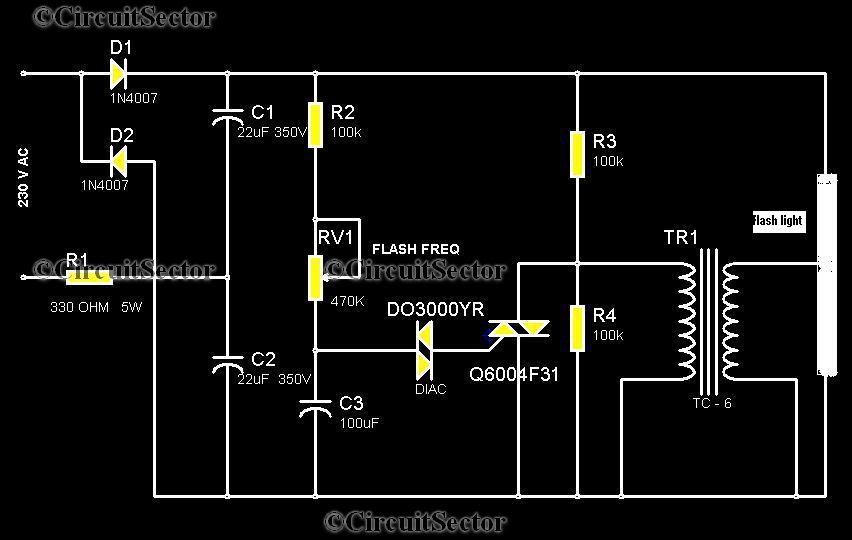
This circuit is a strobe light that allows for adjustable flashing rates. It utilizes a flash tube commonly found in cameras. In standard cameras, the flash may take ten to twenty seconds to recharge. However, this circuit enables the...
Low distortion bass and treble control for an amplifier. Circuit diagram. Electronics project. The low distortion bass and treble control circuit is designed to enhance the audio quality of an amplifier by allowing precise adjustments to the low and high-frequency...
This device is a highly effective capacitive sensor. In North America, it is primarily utilized for detecting wooden beams behind drywall or plaster. This model is preferred over newer designs due to its reliability, as it does not frequently...
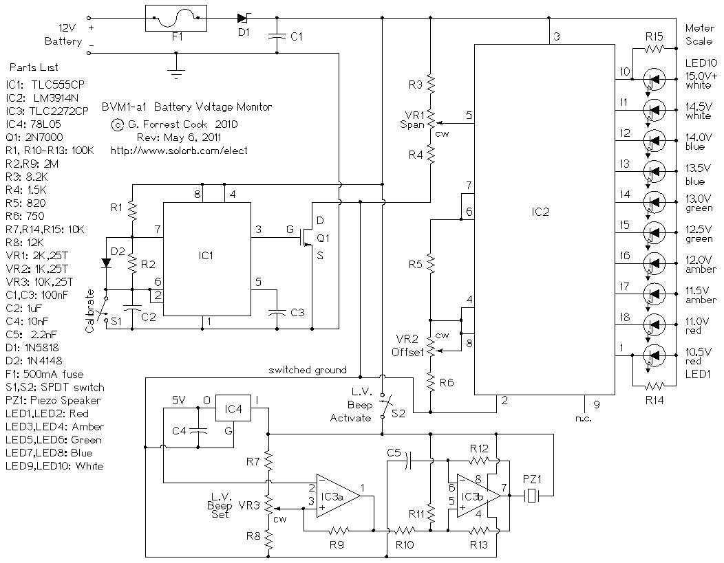
This circuit provides an audible and visual low voltage warning for 12V battery powered devices. When the battery voltage is above the set point (typically 11V), the circuit is idle. If the battery voltage should fall below the set...
The ISL97676 can be utilized as an LED driver capable of managing six channels of LED current for TFT displays. This driver supports the operation of up to 78 LEDs with a voltage range of 4.5V to 26V, or...
This 300W RF power amplifier for an FM transmitter utilizes 2 x TP9383 transistors. It operates within the 88 - 108 MHz frequency band. The 300W RF power amplifier is designed specifically for FM transmission applications, providing high power output...
Warning: include(partials/cookie-banner.php): Failed to open stream: Permission denied in /var/www/html/nextgr/view-circuit.php on line 713
Warning: include(): Failed opening 'partials/cookie-banner.php' for inclusion (include_path='.:/usr/share/php') in /var/www/html/nextgr/view-circuit.php on line 713