
Tone-alert decoder
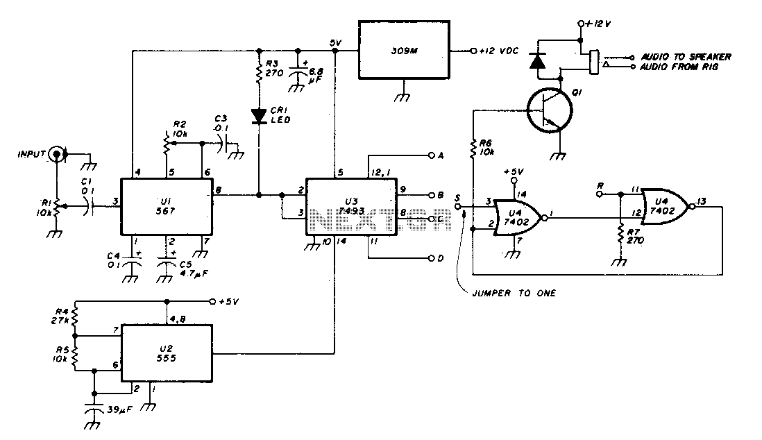
The described circuit utilizes a Phase-Locked Loop (PLL) mechanism to maintain synchronization with a reference signal, which is crucial for applications requiring precise frequency control, such as audio signal processing. The PLL circuit is configured with an external resistor (R2) that sets the frequency of operation. The LED indicator serves as a visual confirmation of the PLL's lock status, which is essential for troubleshooting and operational verification.
To fine-tune the PLL's frequency locking, the circuit incorporates a feedback loop where the signal level is adjusted using resistor R1. This adjustment process ensures that the PLL can lock onto the desired frequency reliably. The output from counter U3 provides a timing signal that introduces a delay, allowing for the stabilization of the PLL before activating the audio output.
The activation of transistor Q1 is a critical function of the circuit, as it controls the flow of audio signals to the speaker. The latch mechanism ensures that audio is only output when the PLL has achieved the correct frequency and duration, preventing unwanted noise or signal artifacts from reaching the speaker.
For reset functionality, the circuit design includes a provision to apply a temporary positive voltage to the R input of U4. This reset action is necessary for reinitializing the latch state, allowing the circuit to restart the frequency detection and locking process as needed. Overall, this configuration offers a robust solution for achieving reliable audio output based on precise frequency control.PLL (Ul) is set with R2 to desired tone frequency. LED lights to indicate lock-up of PLL. Reduce signal level (Rl) and readjust R2 to assure lock-up. Delay is selected from counter U3 output. Circuits latches (turns on Q1 to allow audio to speaker) when proper frequency/duration signal is received To reset latch, a positive voltage must be applied briefly to the R input of U4. 🔗 External reference
Related Circuits
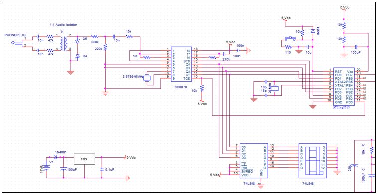
The MT8870 is a complete DTMF receiver that integrates both the band-split filter and digital decoder functions. The filter section employs switched capacitor techniques for high and low group filters, while the decoder utilizes digital counting methods to detect...
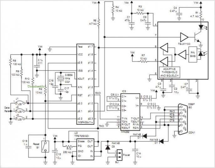
The main system consists of the user interface and control system. The phone line was selected as the interfacing method due to its advantages in long-distance communication. The subsequent image provides a block diagram for both the remote access...
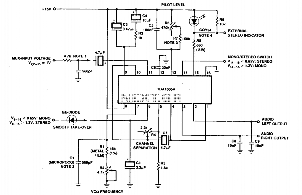
The circuit depicted includes an RC filter (Figure T). The micropico capacitor has a temperature coefficient of 125 x 10^-6 at 60 x 10^-6°C. In simplified circuits, a fixed resistor, such as 620kΩ, can be utilized to ensure a...
This is an image Schematic. No Description available. The provided input indicates that there is a schematic image, but no additional descriptive information is available regarding its components, functionality, or application. In the context of electronic schematics, such images...
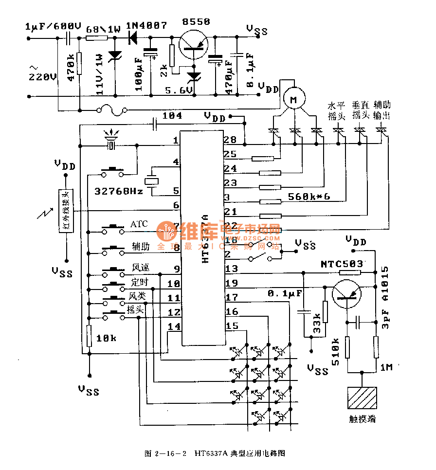
The HT6337 is an infrared remote control receiving decoder circuit specifically designed for electric fan applications. It is housed in a 28-pin dual-row DIP package, with the compatible model being HT12C. The HT6337 is part of a series of...
The decoder is intended to be a reference quality prototype with maximum flexibility for experimental use with different speaker layouts. A new improved version has been added at the end. There are two main sections to the instrument. The...
Warning: include(partials/cookie-banner.php): Failed to open stream: Permission denied in /var/www/html/nextgr/view-circuit.php on line 713
Warning: include(): Failed opening 'partials/cookie-banner.php' for inclusion (include_path='.:/usr/share/php') in /var/www/html/nextgr/view-circuit.php on line 713