
Tone Control Schematic
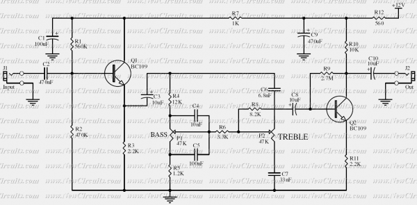
The Baxendall tone control circuit is a widely utilized configuration in audio applications for adjusting the tonal quality of sound signals. It typically consists of a series of resistors and capacitors arranged to provide frequency-dependent gain adjustments. In this specific implementation, the circuit allows for a maximum cut and boost of approximately 10dB at both 10kHz and 50Hz, which are common frequencies of interest in audio processing.
The first transistor, designated as Q1, is configured in a common-collector (also known as an emitter follower) arrangement. This configuration is essential as it provides high input impedance while offering low output impedance, effectively isolating the tone control section from the subsequent stages of the circuit. This buffering capability is crucial in preventing loading effects that could alter the frequency response of the tone control.
The second transistor, Q2, is employed to provide a slight gain boost to the output signal. However, it is important to note that the overall gain of the Baxendall circuit is inherently less than unity due to its passive nature; the tone controls themselves do not amplify the signal but rather adjust the frequency response. The design is optimized to interface with amplifiers that have input impedances ranging from 10kΩ to 250kΩ, ensuring compatibility with a wide range of audio equipment.
The passive nature of the Baxendall circuit means that it relies on the reactive components (capacitors and inductors) to shape the audio signal rather than active amplification. This results in a smooth tonal adjustment without introducing significant distortion, making it a preferred choice in high-fidelity audio applications. The careful selection of component values will dictate the precise frequency response, allowing for tailored adjustments to suit specific audio characteristics.Based on the classic Baxendall tone control circuit, this provides a maximum cut and boost of around 10dB at 10KHz and 50Hz. As the controls are passive, the first transistor, Q1, is configured as common-collector to act as a buffer stage.
The last transistor, Q2, provides a slight boost. Note that the gain of the output of the Baxendall circuit is less than one because of passive nature of it. The output is designed to feed an amplifier with input impedance of 10kohms to 250kohms. 🔗 External reference
Related Circuits
This circuit is an automatic street light controller. The sensor used to detect changes in light is an LDR (Light Dependent Resistor). The working principle of the LDR is that when exposed to light, its resistance value decreases, while...
Temperature indicators and temperature-based products have garnered significant interest due to their numerous applications and various possible solutions, each presenting unique advantages and disadvantages. This concept focuses on a sensor interface that delivers high accuracy while minimizing board space....
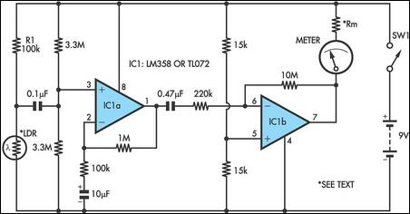
Strictly speaking, this simple circuit should not work. How could anyone expect an ordinary light-dependent resistor (LDR) photocell to detect the change in blood flow as the heart pulsates through a fingertip in natural daylight? The secret lies in...
The tuner is programmable via I²C-Bus and provides a FBAS signal at its output. There is also the homepage of Georg Acher containing information about this tuner. A control circuit has been developed for this tuner using the AT89C2051...
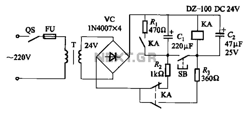
After the turn-off circuit is first applied to the next KA KA, the intermediate interval required is less than Is. This is due to the time needed, which is equal to three times the charge time constant of the...
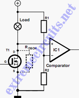
In applications where a MOSFET is used to switch a load, it is relatively straightforward to incorporate short-circuit or overload protection. This can be achieved by utilizing the internal resistance RDS(ON), which generates a voltage drop proportional to the...