
heart rate monitor schematics
The described circuit utilizes a light-dependent resistor (LDR) to monitor blood flow changes due to pulsations in the heart. The LDR operates by varying its resistance based on the amount of light it receives; in this application, it detects subtle changes in light caused by blood flow beneath the skin. The circuit's design hinges on the operational amplifier's ability to amplify these minute signals effectively.
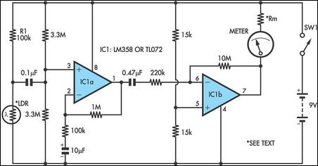
The first stage of amplification is achieved through IC1a, where the LDR and a resistor form a voltage divider. The output from this stage is significantly amplified before being processed by IC1b, which further enhances the signal. The dual op-amp configuration allows for high gain without excessive noise, ensuring that even small fluctuations in blood flow can be detected and displayed on the analog meter.
The choice of components is critical for optimal performance. The use of a 100 kΩ resistor (R1) in series with the LDR is essential for setting the initial operating point of the circuit. The high impedance voltage divider, made from two 3.3 MΩ resistors, ensures that the input to IC1a remains stable and responsive to changes in the LDR's resistance. The capacitors used in the circuit (0.1 µF and 0.47 µF) serve to block any DC component while allowing the AC signal, which corresponds to the heartbeat, to pass through.
The output stage, IC1b, is configured as an inverting amplifier, which not only amplifies the signal further but also inverts it, allowing for a broader range of display options on the analog meter. The inclusion of a current-limiting resistor in series with the meter is a precaution to prevent damage during operation.
This circuit is designed for simplicity and ease of use, making it accessible for educational purposes or hobbyist projects. However, attention must be paid to the environmental conditions in which it is used, as factors such as ambient temperature and light can affect its performance. The method of measuring the heart rate by counting the meter fluctuations over a short period and extrapolating to a minute provides a straightforward approach to monitoring cardiovascular health.Strictly speaking, this simple circuit shouldn`t work! How could anyone expect an ordinary light dependent resistor photo cell to `see` through a fingertip in natural daylight and detect the change in blood flow as the heart pulsates The secret is a high gain circuit, based on a dual op amp IC which can be either the low power LM358 or the JFET T L072. The LDR is connected in series across the 9V battery supply via a 100kO resistor (R1) and the minute signal caused by the blood pulsing under the skin is fed to the non-inverting (+) input, pin 3, of IC1a via a 0. µF capacitor. Pin 3 is biased by a high impedance voltage divider consisting of two 3. 3MO resistors. The feedback resistors to pin 2 set the gain to 11 times. The output of IC1a is fed via a 0. 47 µF capacitor and 220kO resistor to IC1b. This is configured as an inverting op amp with a gain of 45 so that the total circuit gain is about 500.
The output of IC1b is used to drive an analog meter which may be a multimeter set to the 10V DC range or any panel meter in series with a resistor to limit the current to less than its full-scale deflection. The prototype used an old VU meter with a 47kO resistor fitted in series. Note that the unit was designed to use the Dick Smith Electronics light dependent resistor (Z-4801). Other LDRs may require a change in the value of resistor R1. A light source such as a high brightness LED is not required. All that is needed is a reasonably well-lit room, preferably natural daylight, to produce a healthy swing of the needle.
Only when the hands are very cold does it make it a little more difficult to accurately count the pulses. To check your heart rate, carefully position your thumb or finger over the LDR and count the meter fluctuations for a period of 15 seconds.
Then multiply the result by four to obtain your pulse rate. The circuit can not be used if you are walking or running, etc. 🔗 External reference
Related Circuits
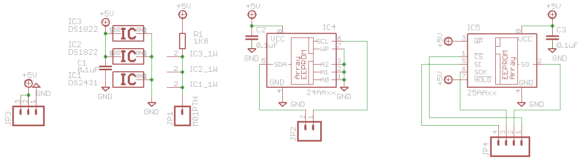
This is an outdated version; refer to the latest version on the documentation wiki. If you have one of Hack a Day's Bus Pirates, what should you do with it? Explore 1-Wire, I2C, and SPI EEPROMs using the 3EEPROM...
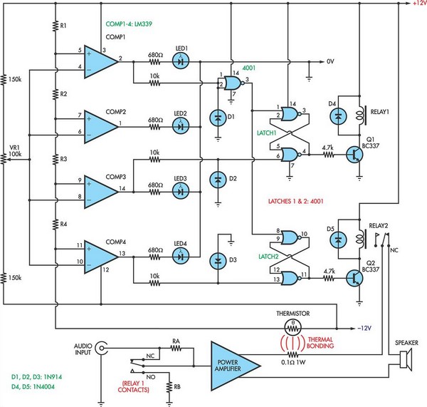
When the voltage on the non-inverting input of each comparator exceeds the voltage at its inverting input, the output transitions to a high state, activating the corresponding LED. NOR gate latches are connected to the outputs of the third...
This is a birthday heart circuit. No much description is available but you can use your experienced imagination! The birthday heart circuit is designed to create a visually appealing display, often used as a decorative element for celebrations. The circuit...
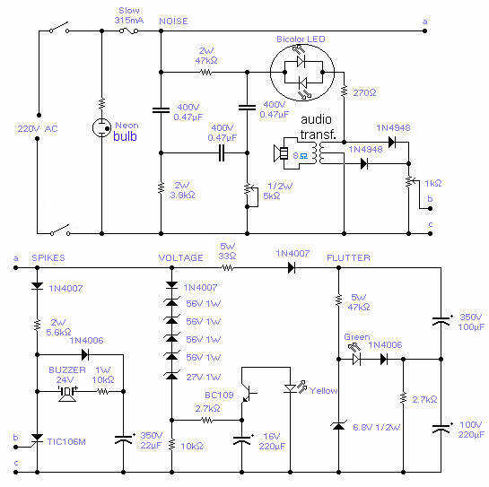
With this circuit you will be able to monitor the quality of the mains. There are 4 distinct sections, each supervising a parameter pertinent to the quality of the supply line. The noise section consists of a 50Hz filter...
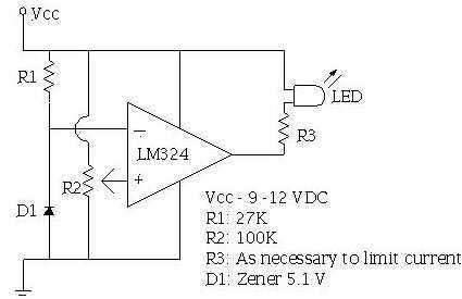
An ECU must have a way to monitor battery voltage. Here is a simple op-amp based circuit which will illuminate the LED when the battery voltage drops to a certain level. The turn-on point is set with R2. You...

If a page name is not selected by pressing the button, the previously selected page name continues to be used. The value is stored in EEPROM and may be changed at any time. When the unit is first powered...