
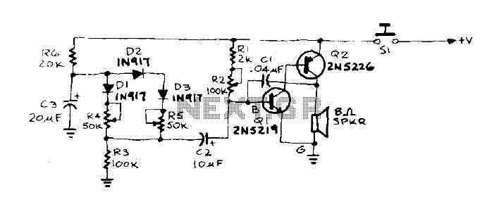
Tone Doorbell circuit
When this activation occurs, the value of RBG aligns with resistor R4. As a result, the total resistance RBG decreases, causing the tone output frequency to increase. Capacitor C3 continues to charge until the voltage across diodes D2 and D3 prompts them to conduct. At this point, RBG is also paralleled by resistor R5, leading to a further decrease in total resistance, which in turn causes the oscillator frequency to increase once more.
The circuit operates as follows: when the door is engaged, the transitioning whisper is generated by an oscillator circuit that relies on the interplay between capacitors and resistors to modulate frequency output. The coupling capacitor C1 plays a critical role in determining the oscillator frequency, while the configuration of resistances, including RBG, Ri, R2, R4, and R5, influences the charging dynamics of capacitor C3.
The operation begins with switch S1 being closed, allowing current to flow and charge capacitor C3 through resistor R6. The initial adjustment of resistor R2 ensures that the frequency starts at a low, pleasant tone. As capacitor C3 charges and reaches a sufficient voltage, diode D1 conducts, effectively reducing the resistance seen by the oscillator circuit. This reduction in resistance results in an increase in frequency output, leading to a higher-pitched tone.
The charging of capacitor C3 continues until the voltage across diodes D2 and D3 becomes sufficient to activate them. The conduction of these diodes introduces additional pathways for current, further lowering the effective resistance in the circuit by paralleling R5 with RBG. This cascading effect of resistance reduction leads to a continuous increase in oscillator frequency, creating a dynamic auditory experience as the tone transitions from low to high frequencies.
In summary, the described circuit utilizes a combination of capacitive charging and resistive feedback to create a variable frequency output triggered by the action of pushing the door. The careful selection and configuration of components ensure a smooth transition in tone frequency, enhancing the user experience with an engaging auditory signal.When the door is pushed, you hear a whisper that "slide up" to a higher frequency. The oscillator frequency is determined by AF coupling capacitance, C 1 and the value of the resistor connected between the base of IQ and the earth. This resistance, RBG is equal to (Ri + R2) RJ. First, suppose that 51 is closed and R2 have been adjusted to produce a pleasant, low frequency tone.
The capacitor C3 charges through R6 until it reaches such a tension that will cause diode Dl to conduct. When this occurs, the value of RBG is consistent with R4. Thus, because the total decrease resistance RBG, tone output slides upward in frequency. The capacitor C3 continues to charge until the voltage across D2 and D3 causes the diodes to conduct. Then RBG is also paralleled by R5, the total resistance decreases again, and the oscillator frequency increases again.
🔗 External reference
Related Circuits
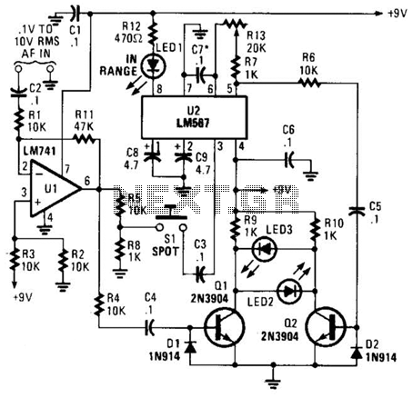
This meter is unique as it does not utilize a D'Arsonval movement or digital display for frequency readings. Instead, the measured frequency is indicated on a hand-calibrated dial. Any audio signal applied to the circuit is amplified by U1,...
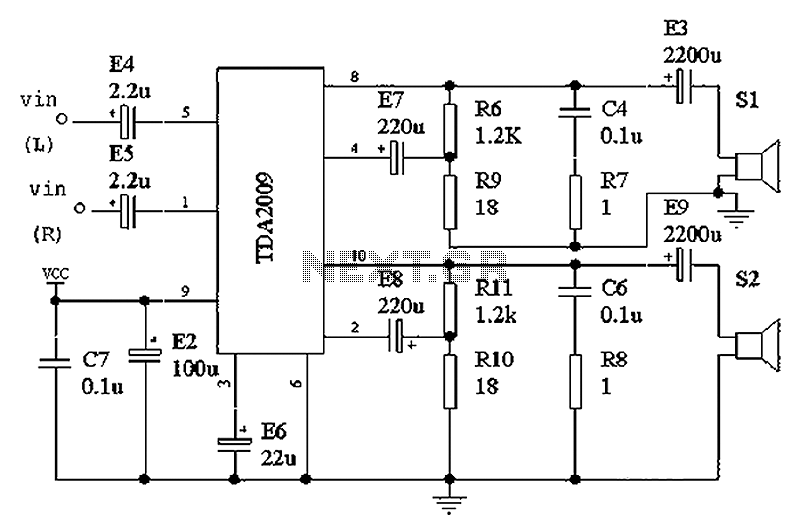
The intention was to develop a morning exercise machine, but the challenge was the absence of a suitable high-power amplifier. Since the exercise machine operates on battery power, the search for a solution persisted for several months. Eventually, the...

The schematic includes programmable AVRs. For other members of the AVR family or additional programmable ICs compatible with Ponyprog, there is a J1 connector (CON10) that facilitates hardware expansion of the programmer. Additional information about compatible ICs can be...
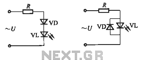
Light-emitting diodes (LEDs) can be powered using direct current (DC), alternating current (AC), and pulse drivers. A typical buck LED display circuit is illustrated in Figure 13-1. The current-limiting resistor (R) for LED tubes can be calculated using the...
3V battery-powered circuit that emits a beep after a fixed delay of several minutes. This circuit was created in response to requests from users seeking a timer functionality. The described circuit operates on a 3V power supply, making it suitable...
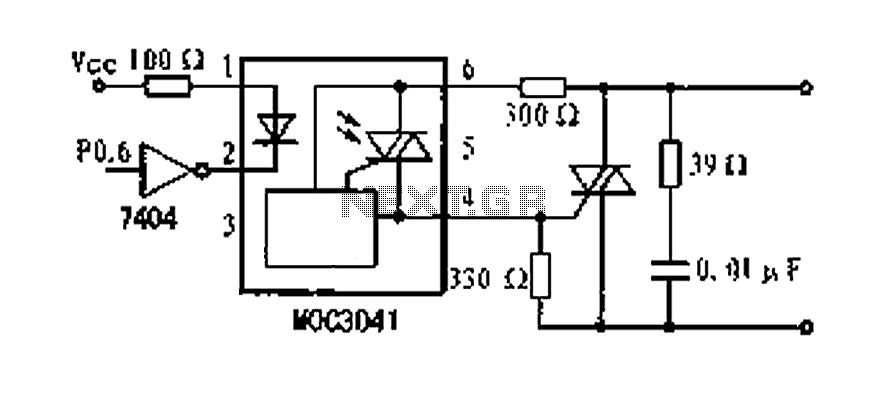
A dimming control circuit is implemented using a single-chip I/O port sinking method to control a thyristor switch for dimming functionality. The MOC3041 optocoupler features an internal zero-crossing detection circuit, allowing for effective control of the thyristor. This design...