
Audio-Frequency Meter Circuit
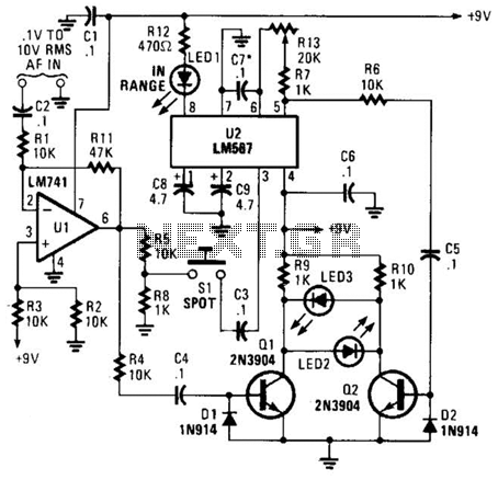
This unique frequency meter employs a combination of analog and digital techniques to achieve accurate frequency measurement without relying on conventional display methods. The circuit begins with an audio signal input, which is amplified by operational amplifier U1. The output from U1 is split into two distinct paths. The first path directs the signal to a mixer circuit, which is responsible for combining the input frequency with a reference frequency. The second path involves a pushbutton switch S1, which, when pressed, allows a portion of the output from U1 to be routed to the input of U2, another operational amplifier configured as an oscillator.
The toggling action of transistor Q1, driven by the signal fed from the mixer, allows for the detection of frequency variations. When the signal is within the operational range of U2's internal oscillator, it triggers LED1, indicating a successful frequency match. The system utilizes feedback from the mixer to ensure that both signals are synchronized. If they are not, LED2 and LED3 illuminate, signaling the need for adjustment.
The fine-tuning process is critical for achieving high accuracy. By releasing S1 and adjusting the variable resistor R13, the user can calibrate the circuit until the indicators (LED2 and LED3) turn off, signifying that the input signal frequency has been accurately matched to the reference frequency. The final reading is displayed on the hand-calibrated dial, providing a precise frequency measurement within a tolerance of 1 Hz. This design emphasizes user engagement through manual calibration while maintaining high accuracy and functionality in frequency measurement applications. This meter differs from the norm in that it does not use a D`Arsonval movement or digital display to give a reading of the input frequency. Instead, the measured frequency is read from a hand-cali-brated dial. Any audio signal applied to the circuit is amplified by Ul and the resulting output is divided along two paths.
In one path, the output signal is applied to the mixer; in the other path, the signal is applied to the input of U2 through SI (a normally open pushbutton switch). The portion of the amplifier signal that is fed to the mixer is applied to the base of Ql, causing it to toggle on and off at the signal frequency.
In the other path, when SI is pressed, a portion of the op amp`s output is applied to U2. If the signal is within the range of U2`s internal oscillator`s operating frequency, LED1 lights, and a signal is fed to the base of Q2. If the two signals arriving at the mixer do not match exactly, LED2 and LEDS light. That means that the circuit must be fine tuned, which is accomplished by releasing SI and fine tuning R13 until LED2 and LED3 go out.
The dial setting at that point gives the frequency of the input signal to within 1 Hz (or as close as the calibrated dial will allow). 🔗 External reference
Related Circuits
The circuit diagram presented is for an IC controlled emergency light with a charger, functioning as a 12V to 220V AC inverter circuit. Key features include automatic activation of the light during a mains failure and a battery charger...
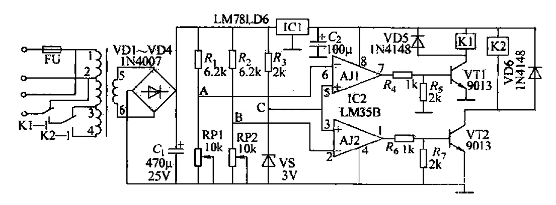
The AC power supply circuit primarily consists of a power supply, a reference voltage, a voltage comparator for sampling, and several other components. It includes a transformer for the input, an autotransformer tap for the control power supply circuit,...
In the circuit, when E and O are input DC voltages, the motor moves to a position corresponding to the voltage. A potentiometer, coaxially connected to the motor, is used for position feedback. When the given voltage equals the...
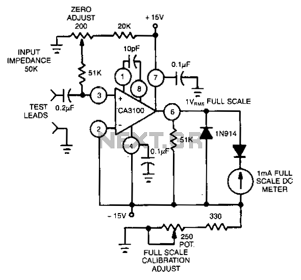
This circuit utilizes the CA3100 BiMOS operational amplifier to drive a 1-mA meter movement to its full scale with a 1-V RMS input. The circuit configuration incorporates the CA3100 BiMOS operational amplifier, which is known for its high input impedance...
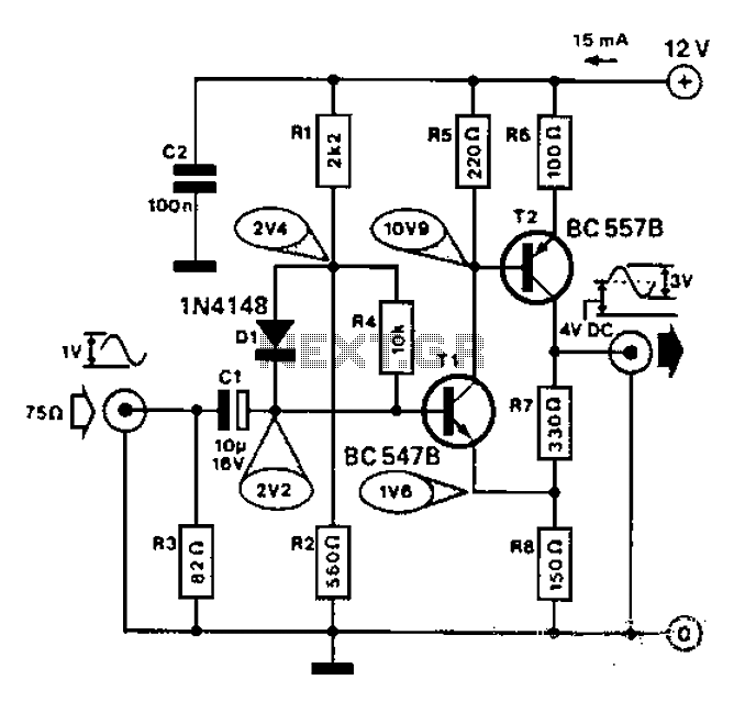
Commonly used for cameras or computers with black and white television connections, the amplifier has a gain of 3 and a bandwidth of 10 MHz. The described circuit is an amplifier designed for applications involving cameras or computers that interface...
This PC fan controller circuit is designed with discrete components to control 12V fans that consume less than 200mA. The specified component values in the circuit diagram ensure that the voltage will not drop below 7V. If the fan...
Warning: include(partials/cookie-banner.php): Failed to open stream: Permission denied in /var/www/html/nextgr/view-circuit.php on line 713
Warning: include(): Failed opening 'partials/cookie-banner.php' for inclusion (include_path='.:/usr/share/php') in /var/www/html/nextgr/view-circuit.php on line 713