
Tone generator

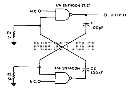
The described circuit employs the 555 timer IC, a versatile component commonly used in various timing applications. In this configuration, the circuit can be set up in astable mode, where the timers continuously switch between high and low states, creating a square wave output. This output can be manipulated to produce a warbling effect, which is characterized by a periodic rise and fall in frequency.
Capacitor C1 plays a crucial role in determining the frequency of oscillation. By selecting an appropriate value for C1, the speed of the warble can be adjusted, allowing for a range of effects from slow, drawn-out oscillations to rapid, fluttering signals. The time period of the oscillation is influenced by both C1 and the resistors connected to the timing pins of the 555 timer.
Capacitor C2, on the other hand, is responsible for setting the pitch of the output signal. The pitch can be altered by changing the capacitance of C2, which affects the duty cycle and the overall frequency of the output waveform. The interaction between C1 and C2 allows for a rich variety of sound modulation, making this circuit suitable for applications such as sound synthesis or alarm systems.
The values of the components used in the circuit are critical to achieving the desired distinctive signal. Careful selection of resistors and capacitors will yield a wide range of audible tones and effects. Properly tuning these components can result in a unique sound that stands out in various applications, from musical instruments to electronic sound effects.
In summary, this circuit design utilizing 555 timers offers flexibility and creativity in sound generation, with capacitors C1 and C2 serving as key elements in controlling the warble speed and pitch, respectively.The circuit uses a pair of 555 timers or a single dual timer. Capacitor Cl controls the speed of the warble, while C2 determines the pitch. The values shown should produce quite a distinctive signal.
Related Circuits
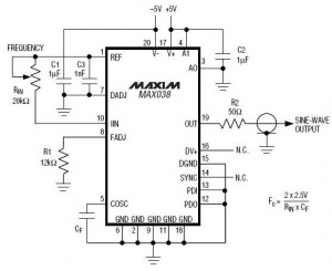
A high-frequency waveform generator is highly beneficial for electronic experimentation and design. This circuit generates sine wave oscillations; however, it can be modified to produce triangle or square wave functions. The frequency can be controlled using current. By disconnecting...
Pure sine wave inverters are optimal; however, they are costly to purchase or construct. Modified sine wave inverters can power certain equipment, while square wave inverters have more limitations. Pure sine wave inverters are highly regarded for their ability to...
The LM1036 is a DC-controlled circuit designed for tone adjustment (bass/treble), volume control, and balance. It is suitable for use in car radios, televisions, and audio systems. The circuit also incorporates loudness compensation. The LM1036 integrates several functionalities essential for...
With the values shown, the circuit generates a 2-MHz symmetrical square wave. Changing capacitors C1 and C2 to 0.01 µF results in a frequency of 500 Hz. For the particular integrated circuits and power supply voltages (5.0 V), the...
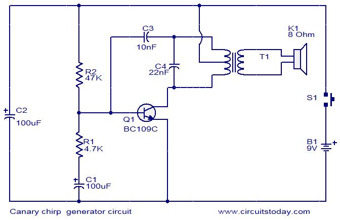
This is a simple electronic alarm circuit that imitates the chirping of a canary. The circuit consists of a Hartley oscillator with a few additional passive components. As capacitor C1 charges through resistor R1, transistor Q1 is driven to...
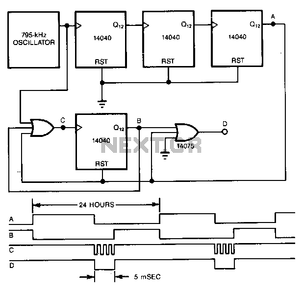
A precise pulse generator can be constructed using a precision oscillator and several CMOS counters. The number of counters can be increased to extend the pulse period as needed. This circuit will generate a pulse approximately 5 ms long...