
2MHz square-wave generator
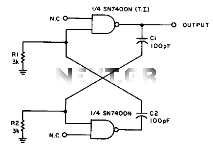
The described circuit operates as an oscillator, generating a symmetrical square wave at a frequency of 2 MHz under standard conditions. The frequency is primarily determined by the values of capacitors C1 and C2, as well as the resistors R1 and R2. When the capacitance of C1 and C2 is adjusted to 0.01 µF, the output frequency decreases to 500 Hz, demonstrating the circuit's versatility in frequency generation.
In this configuration, the integrated circuits used are likely operational amplifiers or a dedicated oscillator IC, which require a power supply voltage of 5.0 V for optimal performance. The resistors R1 and R2 play a critical role in setting the gain and frequency characteristics of the circuit. The specified reliable operating range for these resistors is between 2 kΩ and 4 kΩ, which ensures stable operation and prevents distortion of the output waveform.
The symmetrical square wave produced by the circuit can be utilized in various applications, such as clock signals for digital circuits, timing applications, or as a modulation source in communication systems. The ability to alter the frequency by changing the capacitor values allows for flexibility in design, catering to specific requirements in different electronic applications. Proper selection of components within the specified ranges is crucial for maintaining the desired performance characteristics of the oscillator circuit.With the values shown the circuit generates a 2-MHz symmetrical square wave. Changing capacitors Cl and C2 to 0.01 µ¥ results in a frequency of 500 Hz. For the particular integrated circuits and power supply voltages (5.0 V), the reliable operating range of Rl = R2 is 2 k ohm to 4 k ohm. 🔗 External reference
Related Circuits
This circuit utilizes the versatile MAX038 function generator. While some advanced features of this IC are disabled in this configuration, it is capable of generating sine, triangle, and square waves by adjusting the A0 and A1 pins (refer to...
This circuit generates a two-tone effect similar to the sound of a cuckoo. It can be utilized for doorbells or other applications due to its integrated audio amplifier and loudspeaker. The circuit is designed to produce a distinctive two-tone sound,...
An audio frequency signal generator can output audio signals, 465 kHz spectral amplitude signals, and 52.5 Hz to 16 kHz high-frequency amplitude-modulated signals. The high-frequency oscillator's vibration frequency is determined by the components G and L. A variety of...
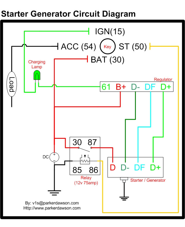
Circuit diagrams for both a Bosch and a Delco-Remy Starter-Generator are available, noting that the circuits differ. Due to a computer crash, the original diagrams and the associated email address were lost. However, in May 2004, both the email...
Sound effects generators trying to imitate rain sound or sea surf are well known to hobbyists from many years: their purpose is to induce relaxation and sleep or to help in concentration and study. The sound generated is restrained...
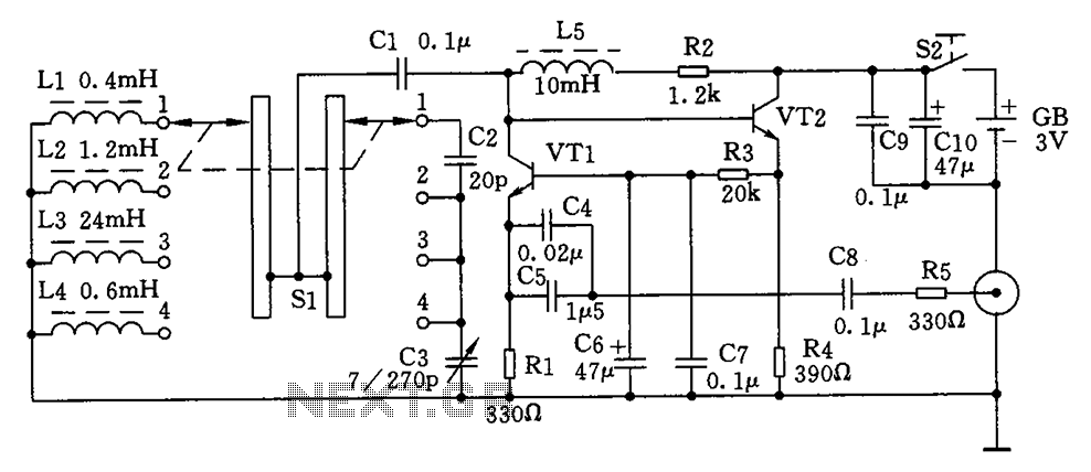
This is a simple high-frequency signal generator. By changing the inductance of the LC resonant circuit using the band switch S1, the high-frequency oscillation frequency range can be altered. The generator is divided into four frequency stages: the first...