
Touch delay switch circuit diagram CD4013 composed
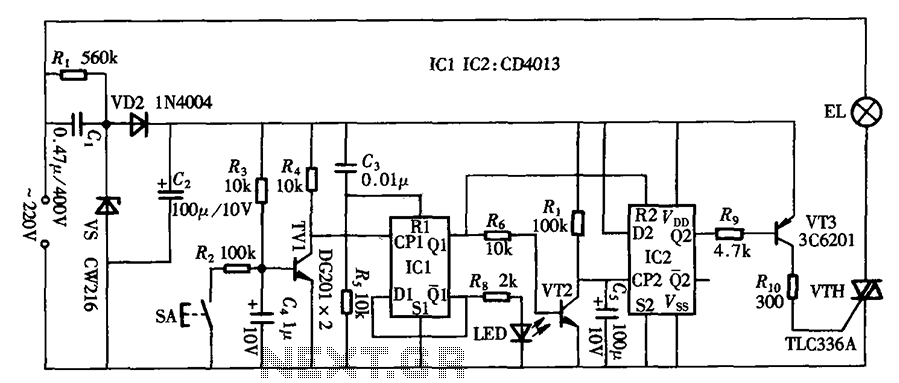
The described circuit employs two D flip-flops from the CD4013 series, which are configured to create a touch-sensitive delay switch. This arrangement allows for the activation of a load, such as a light or machine, with a delay after the initial touch input. The first flip-flop is configured to capture the touch input, while the second flip-flop is utilized to determine the state of the output after the delay period.
The power self-locking function ensures that once the switch is activated, it remains in the 'on' state until it is intentionally reset. This is achieved by feeding back the output of the second flip-flop to the input of the first, creating a latch effect. The circuit can be designed to include additional components such as resistors and capacitors to set the timing for the delay period, allowing for customization based on application requirements.
In practical applications, this circuit can be beneficial for scenarios where a momentary touch is required to activate a device, such as in lighting systems, where the user may prefer a delay before the light turns on, or in machines where a delay is necessary for safe operation. The simplicity of the CD4013 D flip-flops allows for reliable performance in various electronic projects, making it a suitable choice for touch-delay switch designs. As shown mainly by the touch-delay switch one pair of D flip-flop CD4013 composed, it can be used in some machines power switch, delay switch is also used as lighting, it also has power self-locking function, circuit as shown in FIG.
Related Circuits
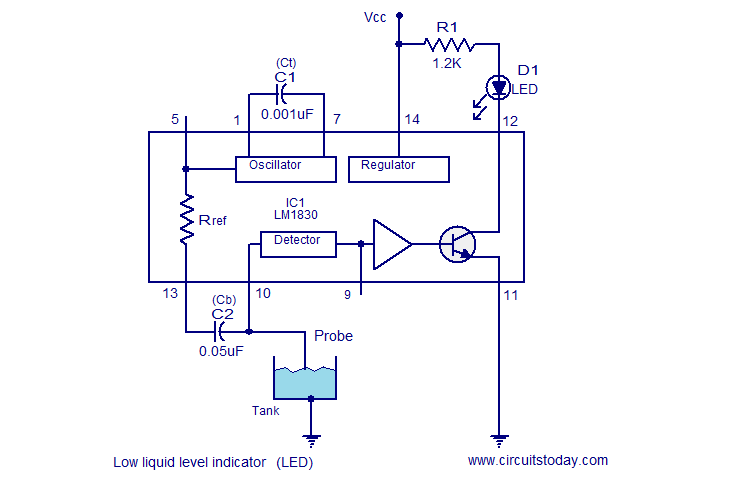
The following circuit illustrates a Liquid Level Sensor Indicator Circuit utilizing the LM1830 integrated circuit. Features: Manufactured by National Semiconductors, the device... The Liquid Level Sensor Indicator Circuit employing the LM1830 IC is designed to detect and indicate the level...
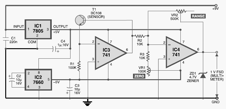
This digital thermometer circuit diagram uses a common 1N4148 diode as the temperature sensor. The temperature coefficient of the diode is -2 mV/°C. The digital thermometer circuit leverages the characteristics of the 1N4148 diode, which has a well-defined temperature coefficient....
This tremolo effect circuit utilizes the XR2206 and the TCA730 integrated circuits, which are designed as an electronic balance and volume regulator with frequency correction. The tremolo effect circuit operates by modulating the amplitude of an audio signal, creating a...
The sustain pedal, also known as the damper pedal, sends a controller value of CC64 when operated. Pressing the pedal results in an output value of 127, while releasing it results in an output value of 0. Tone generators...
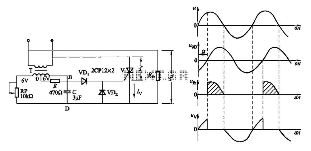
By adjusting the potentiometer RP, the output voltage of the phase shift bridge diagonal changes accordingly, which in turn alters the rectifier load power Rfz. Waveforms at respective points in FIG. 16-1 (b) illustrate this. Resistor R serves as...
Most recent cars are equipped with a significant amount of electronics, including ABS brake systems, engine control with injection calculators, airbag activation, and various comfort functions. One such function, often overlooked due to its commonality, is the automatic activation...