
Single phase half-wave phase-shift trigger circuit resistance-capacitance
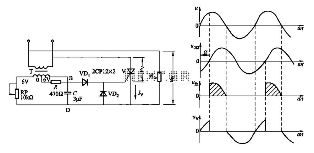
The circuit under discussion utilizes a phase shift bridge configuration, where the output voltage can be finely tuned via a potentiometer (RP). This adjustment directly influences the performance of the rectifier load (Rfz), thereby allowing for precise control over the power delivered to the load. The phase shift bridge operates by manipulating the phase relationship between the input and output signals, enabling effective voltage regulation.
In the circuit, the current limiting resistor (R) plays a crucial role in safeguarding the thyristor gate by restricting the amount of current flowing into it. This is essential for preventing damage to the thyristor, which can occur due to excessive gate current. The design ensures that the thyristor operates within its safe limits, enhancing the reliability and longevity of the circuit.
Additionally, the inclusion of diodes (VDi and VDz) serves as protective elements against reverse voltage spikes. These diodes are configured to prevent breakdown of the control gate by shunting any excessive reverse voltage away from the sensitive components. This protection is vital in circuits where inductive loads may generate back EMF or where transients can occur, ensuring stable operation and preventing circuit failure.
The waveforms depicted in FIG. 16-1 (b) further illustrate the operational characteristics of the circuit at various points, providing insight into the dynamic response of the system as the potentiometer is adjusted. This visual representation aids in understanding the relationship between the input adjustments and the resultant output behavior, making it easier to analyze and optimize the circuit performance.Adjusting potentiometer RP, the output voltage of the phase shift bridge diagonal oD phase change accordingly, thus obtained Rfz rectifier load power is also changed accordingl y. Waveforms at respective points in FIG. 16-1 (b) shown in the figure, R is the current limiting resistor to limit the thyristor gate current V; diode VDi, VDz to protect the control -gate from excessive reverse voltage breakdown.
Related Circuits
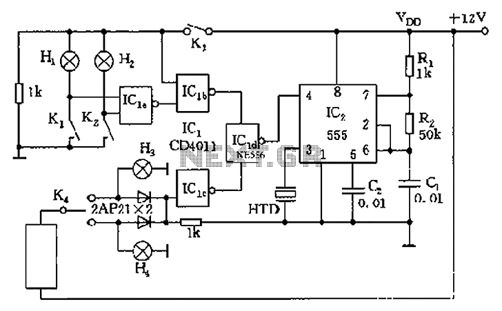
The circuit presented is a 555 timer-based alarm system for vehicles, which primarily consists of a 555 timer and a quad 2-input NAND gate configuration. It is designed to produce a long beep sound when oil pressure is low...
This is a stereo power amplifier circuit that operates at up to 22W per channel, resulting in a total output of 2x22W. A few external components are required to support the main component, the TDA1554. A heatsink on the...
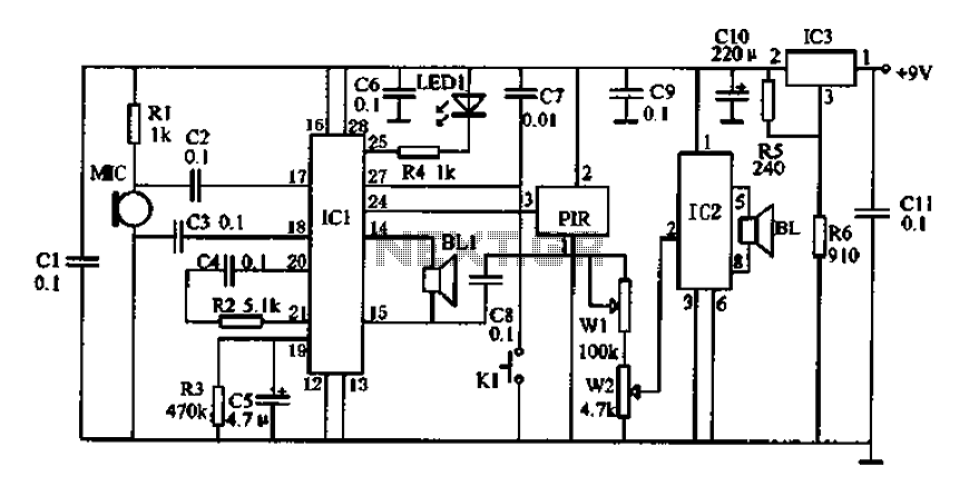
Doppler effect sensor N1 (RD627), operational amplifier N2 (LM358), and a special integrated circuit for imitating dog barking (N3, KD5608) are utilized along with other components. When there is no activity detected in the monitoring area by N1, the...
The circuit comprises a 3-stage resistor-capacitor coupled amplifier. When ring button S2 is pressed, the amplifier circuit formed around transistors T1 and T2 gets converted into an asymmetrical astable multivibrator generating ring signals. These ring signals are amplified by...
Here is an interesting circuit for a magnetic proximity switch which can be used in various applications. The magnetic proximity switch circuit, in principle, consists of a reed switch at its heart. When a magnet is brought in the...
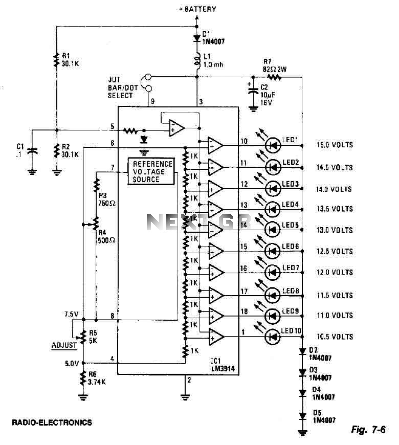
This screen utilizes ten LEDs to indicate a voltage range from 10.5 to 15 volts, with each LED corresponding to a 0.5-volt increment. The core component of the circuit is the LM3914 LED bar graph/display driver. A trimming potentiometer,...
Warning: include(partials/cookie-banner.php): Failed to open stream: Permission denied in /var/www/html/nextgr/view-circuit.php on line 713
Warning: include(): Failed opening 'partials/cookie-banner.php' for inclusion (include_path='.:/usr/share/php') in /var/www/html/nextgr/view-circuit.php on line 713