
Touch Switch Monostable/Timer with 555 IC
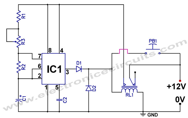
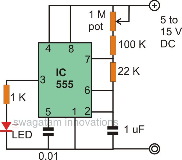
The touch switch circuit operates by utilizing the 555 timer in monostable mode, where the timer generates a single pulse when triggered by the touch terminal. The touch terminal acts as a momentary switch that, when activated, sends a signal to the timer, initiating the timing sequence. The one-shot multivibrator, connected to the 555 timer, ensures that a single output pulse is generated for a predetermined duration, defined by the resistor (R3) and capacitor (C2) values.
The output of the circuit can be interfaced with various components such as power transistors, CMOS circuitry, hexFET transistors, or optocouplers, allowing for a wide range of applications, including LED control, relay activation, or other electronic device management. The selection of the output stage component depends on the required load current and voltage specifications.
The timing characteristics of the circuit are governed by the formula: T = 1.1 * R3 * C2, where T is the time duration for which the output remains high. By adjusting the resistance of R3 or the capacitance of C2, the ON time can be finely tuned to meet specific application requirements. Increasing either component will result in a longer ON time, providing flexibility in the design and functionality of the touch switch circuit. Conversely, reducing the values will decrease the ON time, allowing for quicker response times in applications where rapid switching is desirable.
Overall, this touch switch circuit exemplifies a versatile and efficient method for controlling electronic devices through a simple touch interface, leveraging the reliable performance of the 555 timer and the configurability of passive components.A schematic diagram of a touch switch circuit is shown below. This circuit consist of timer, one shoot multivibrator and touch terminal. As timer, this circuit uses 555 timer which is connected to one-shot multivibrator. The touch terminal is used to trigger this circuit. The output of this circuit can be used to drive a power transistor, CMOS ci rcuitry, hexFET transistor or optocoupler. Here is the schematic diagram of the touch switch circuit: Using the given values as shown in the schematic diagram, this circuit has timed ON period of 4 seconds. The value of C2 and R3 determines the ON time, increasing the value of C2 or R3 will increase the ON time.
The ON time is decreased if the value of C2 or R3 is decreased. 🔗 External reference
Related Circuits
The standard 555 timer circuit consumes power from the battery even when the start push-button (PB1) is not pressed, due to a potential divider created by three 5kΩ resistors within the integrated circuit (IC). This power consumption, referred to...
Each audio/video output can be switched to any of the eight inputs separately. One module drives one audio/video output and has a 34-pin connector to plug into the system interface. Video operational amplifiers (OPAs) can be used on the...
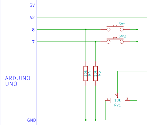
Flicker-free updating of analog input and the status of switches using Ajax and the Arduino Ethernet Shield. The Arduino Uno is configured as a web server. The described system utilizes an Arduino Uno microcontroller, which operates as a web server...
The astable multivibrator mode is the most basic operational mode of the IC 555. In this mode, it functions as a free-running oscillator. When the oscillator rate is sufficiently reduced, it can be used to drive LED lights. The...
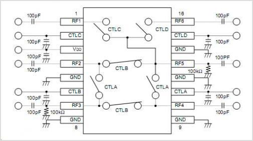
The CYWUSB6953 is a comprehensive Radio System-on-Chip (SoC) device that facilitates the implementation of various simple RF systems using a single chip and a few discrete components. It is specifically designed for low-cost wireless systems that operate within the...
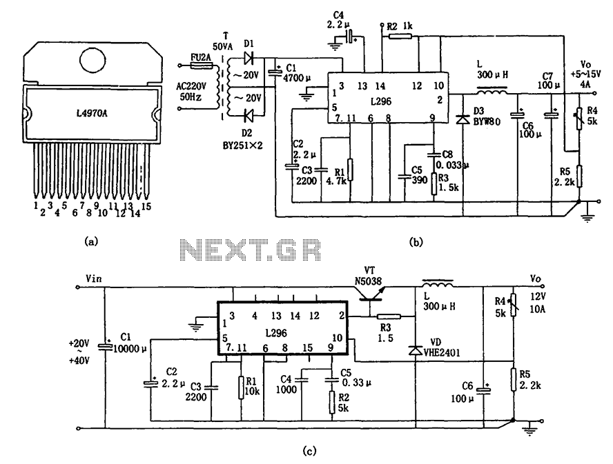
The L296 chip is a high-current switching power supply component designed to operate within a voltage range of 5 to 15V and provide an output current of up to 4A. This monolithic chip incorporates several features including enhanced protection...
Warning: include(partials/cookie-banner.php): Failed to open stream: Permission denied in /var/www/html/nextgr/view-circuit.php on line 713
Warning: include(): Failed opening 'partials/cookie-banner.php' for inclusion (include_path='.:/usr/share/php') in /var/www/html/nextgr/view-circuit.php on line 713