
555 Low power Consumption Timer Circuit
The circuit design utilizes a 555 timer in astable mode, which is a common configuration for generating a continuous square wave output. The inclusion of a double-pole relay enhances the functionality by allowing for efficient power management. The relay contacts are strategically used to control the power supply to both the timer and the load, ensuring that energy is conserved during idle periods. The push-button switch (PB1) serves as the user interface to initiate the timing sequence.
The resistor values and capacitor used in the timing circuit are critical for defining the oscillation frequency. The time constant formula indicates that the timing period can be adjusted by varying the values of R1, R3, and C1. This flexibility allows for customization of the timing intervals based on the specific application requirements.
The diode D1 is essential for ensuring that once the relay is energized, it remains latched until the timing cycle is complete. This prevents the relay from dropping out prematurely and ensures that the load remains powered throughout the duration of the timing operation.
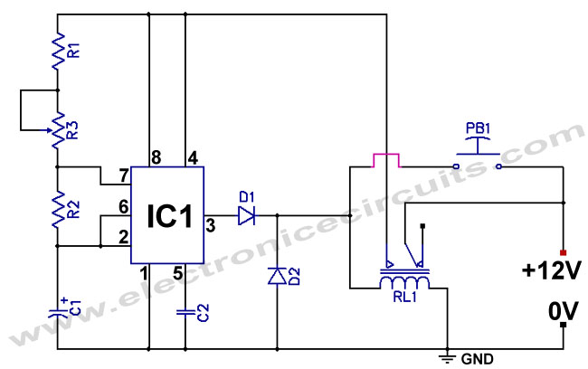
Overall, this circuit design not only addresses the idling power consumption issue associated with traditional 555 timer circuits but also provides a practical solution for applications where battery life is a concern. By implementing this design, the reliability and efficiency of the circuit are significantly improved, making it suitable for various electronic projects.Normally 555 timer circuit even though the start push-button PB1 is not pressed, the timer keeps consuming power From the battery due to a potential divider formed by three 5k © resistors within the IC. this power consumption known as the idling power consumption of the timer is about 3mA. This, if left connected to a battery for a long time can drain off the battery and may give unreliable operation. To deviate this short coming, you may use the circuit given in the below. Which enables power to be drained from the battery only when timing action is ON. For the idling period, the power consumption is zero. The circuit uses a double pole relay. One pole is used to energize the load, the other pole is used to cut off the supply line when the timing action is over. A push on the Start` switch energizes the relay RL1. A pair of contacts of the relay provides the supply voltage to the timer which get triggered. Oscillations start and when the output at pin 3 becomes HIGH, the diode D1 permits current to flow through the relay, thus latching it up.
The frequency of the oscillations depends on the time constant given by T=1. 1G—C1G—(R1 R3). After this time is over, the output at pin 3 goes LOW; the relay is released, and the load is de-energized. We aim to transmit more information by carrying articles. Please send us an E-mail to wanghuali@hqew. net within 15 days if we are involved in the problems of article content, copyright or other problems.
We will delete it soon. 🔗 External reference
Related Circuits
Even if the circuit is simple, it complies with all conditions regarding distortion and frequency response. The input resistance is 250K ohms, and it can drive loads ranging from 100 ohms to 2K ohms. The described circuit is a fundamental...
This appears to be an infrared (IR) transmitter. IR signals do not penetrate walls, and it is assumed that this device is intended for use in a room separate from the one in which the user is located, rendering...
This is a programmable alarm timer circuit that uses LEDs to indicate hours and minutes. Twelve LEDs can be arranged in a circle to represent the 12 hours of a clock face, and an additional 12 LEDs can be...
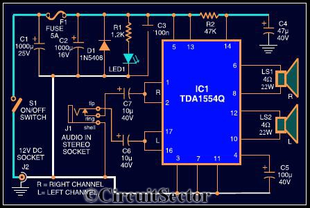
The circuit diagram illustrates a robust stereo amplifier capable of delivering 22W of power. It is based on the widely used single-chip audio power amplifier TDA1554Q (IC1), which is configured as two 22W stereo bridge amplifiers. While listening to...
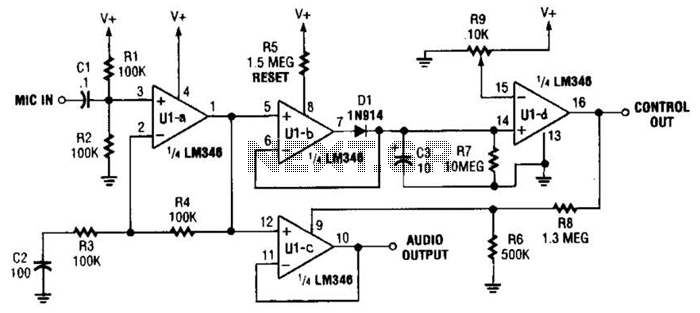
In specific applications, such as transmitters or other communications and control systems, this circuit is designed to be beneficial. It provides both audio output and DC control outputs. Additionally, R9 establishes the control threshold. The circuit in question is versatile...
In this fire alarm circuit, a thermistor functions as the heat sensor. As the temperature rises, its resistance diminishes, and conversely, when the temperature falls, its resistance increases. At standard temperature, the resistance of the thermistor (TH1) is approximately...