
Traffic intersection light automatic controller circuit
The automatic traffic light control circuit is designed to efficiently manage the flow of vehicles and pedestrians at intersections. The use of multiple 555 timer ICs allows for precise timing control of each traffic light phase, providing flexibility in adjusting the duration of each light based on traffic conditions. The initial trigger from IC1 initiates the sequence, with the timing of each light phase determined by the values of the resistors and capacitors connected to the 555 timers.
The circuit's design integrates a voltage regulator (78M05) to ensure a stable supply voltage of +5V, essential for the reliable operation of the 555 timers. The timing components (resistors and capacitors) are selected carefully to achieve the desired delay intervals, which can be customized for different traffic conditions or regulatory requirements.
The monostable configuration of the 555 timers allows each stage of the traffic light sequence to be triggered in succession. The transition from green to yellow to red is managed through a series of timed outputs, ensuring that the lights change in a controlled manner. The use of differential components (C2, R22, C3, R23) provides the necessary signal conditioning to ensure that the transitions between states are smooth and without glitches.
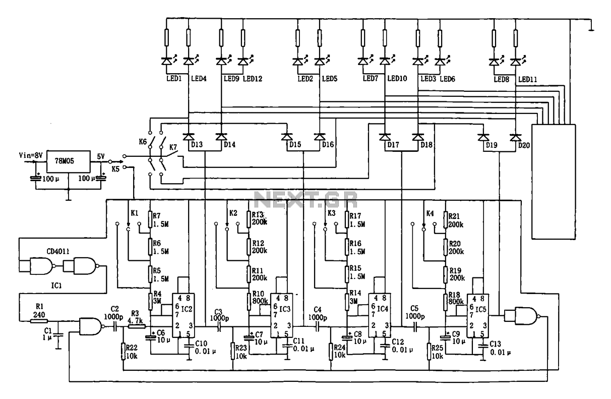
This circuit can be implemented in various traffic management systems, enhancing safety and efficiency at intersections. The adjustable timing settings provide versatility, allowing for adaptation to different traffic patterns and peak hours. Overall, this automatic traffic light control circuit exemplifies a practical application of electronic timing circuits in real-world scenarios.Shown for the automatic traffic intersection traffic light control circuit. Four monostable delay circuit inclusive The controller consists of four 555 (IC2 ~ IC5) and a number of RC components connected together. 8V input voltage through the 78M05 regulator after 555 provide VDD = + 5V supply voltage.Just when the power is turned on, the trigger pulse by IC1 (CD4011) gates and R1, C1 delay, then by C2, R22 differential added IC2 foot trigger IC2 output high into the temporary steady state, the temporary stability state timing varies depending on the position K1, the delay td = 1.1RC6, set time was 60 seconds, 45 seconds, 30 seconds. At the end of the temporary state, IC2 pin low after its C3, R23 differential, falling and trigger IC3, monostable delay the formation of the second stage.
So in turn trigger timing to complete the green light - yellow lights (8 seconds, 10 seconds, 12 seconds) - Red Lights (60 seconds, 45 seconds, 30 seconds) cycle.This circuit is a control circuit monitors the command within the booth and display section. If you really mean for traffic cherry Grubs hoop Bodhisattva lotus Dao Pai Zeon da Hot Sputum Jin sole Slow majority of video game badger Bru Ao Po buttercup The controller circuit by four end to end, turn trigger delay, so the traffic lights turn green appear - yellow - red (color) signals, pedestrians and vehicles in the command I = 1 Crossroads orderly traffic (green) - to draw attention (yellow) - No Entry (red).
Related Circuits
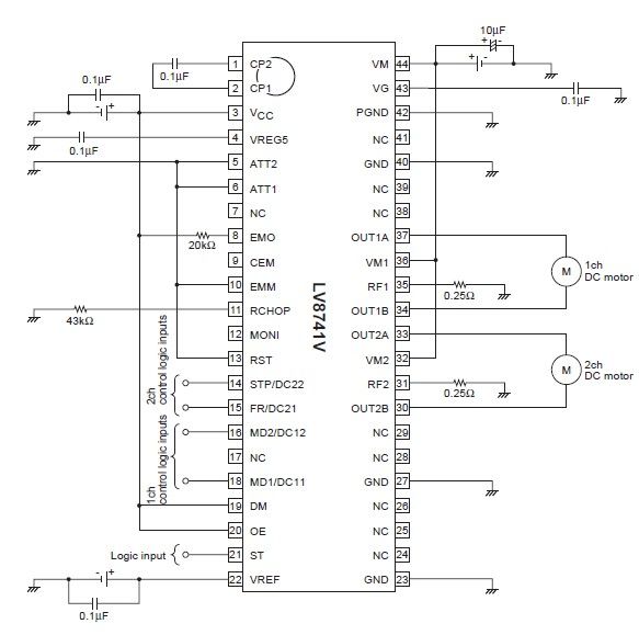
The circuit diagram illustrates an electronic project that requires a few external electronic components. The PWM current-control stepping motor driver IC can provide a maximum output current of up to 1.5 amperes. The configuration settings for the PWM current-control...
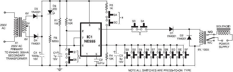
A simple electronic key code lock circuit that requires few external components can be constructed using this schematic diagram. This electronic key code lock circuit is based on a common 555 timer circuit and other standard components. This low-cost...
This circuit is capable of automatically charging 6V and 12V batteries quickly and accurately. A key factor in the successful operation of the circuit is the use of a high-quality transformer (T1) that features excellent insulation and short-circuit resistance. The...
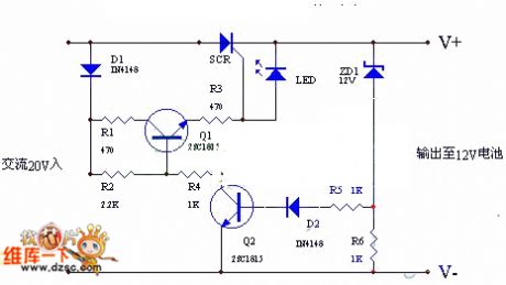
The circuit utilizes the positive half-cycle of an alternating current (AC) to charge a battery. It offers a rapid charging speed and has the potential to extend battery life. This charger is commonly used with standard motorcycles, demonstrating excellent...
Solar panels operate at optimal parameters when positioned at the ideal angle to the sun. This alignment is achieved by rotating the solar panels to track the sun's movement. A DIY solar tracker system can be constructed using an...
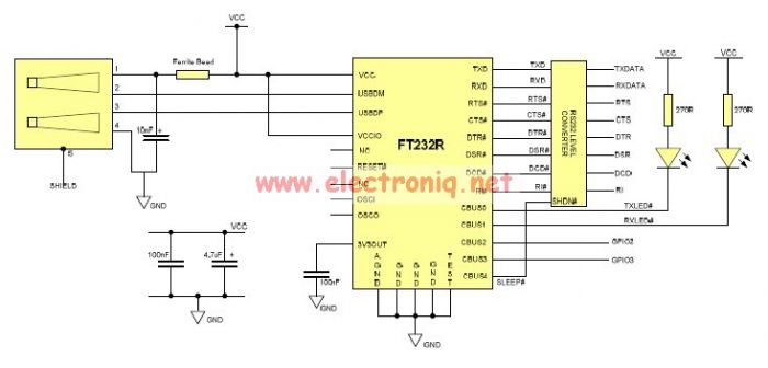
This USB to Serial RS232 adapter is highly beneficial in scenarios where a device with RS232 needs to be connected to a computer lacking an RS232 port but equipped with a USB port. Utilizing the FT232BM chip produced by...