
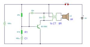
Car Battery 6V or 12V charger circuit
The charging circuit is designed to efficiently manage the charging process of lead-acid or similar batteries, ensuring optimal performance and longevity. The inclusion of transformer T1 is crucial, as it steps down the mains voltage to a lower, safer level suitable for battery charging. The transformer must have a high insulation rating to prevent any risk of electrical shock and must also be robust enough to handle short-circuit conditions without failure.
The circuit typically includes additional components such as rectifiers, voltage regulators, and protection diodes. Rectifiers convert the alternating current (AC) output from the transformer into direct current (DC), which is necessary for charging batteries. The voltage regulator maintains a consistent output voltage, preventing overcharging which could damage the battery. Protection diodes are implemented to prevent reverse current flow, thereby safeguarding the transformer and other circuit components from potential damage.
To enhance charging efficiency, a microcontroller may be integrated into the design to monitor battery voltage and current, allowing for smart charging algorithms that adapt to the battery's state of charge. This feature can help in extending the battery's lifespan by preventing overcharging and optimizing charge cycles.
Overall, the circuit's design should prioritize safety, efficiency, and reliability, ensuring that it meets the necessary standards for battery charging applications. Proper layout and component selection will lead to a robust charging solution suitable for various applications requiring 6V and 12V battery support.This circuit can charge automatically, fast and rightly, batteries 6V and 12V. A basic factor in the success in the circuit operation is the use of transformer [T1] of good quality with very good insulation and resistance in the short circuits.. 🔗 External reference
Related Circuits
The circuit below illustrates powering one or two LEDs from the 120-volt AC line using a capacitor to drop the voltage and a small resistor to limit the inrush current. Since the capacitor must pass current in both directions,...
The laser-pointer detection circuitry is capable of identifying when a laser light is directed at a specific photosensor. If the laser targets the top sensor, the comparator chip outputs a high signal. Conversely, if the laser is aimed at...
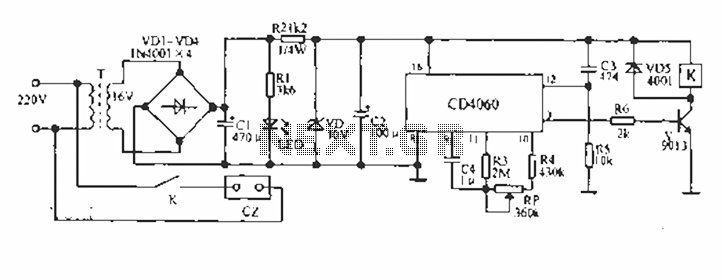
A CD4060 production time controller circuit is illustrated below. It is connected in such a way that R5 and C3 form a differential circuit to create a delay time from the start. Under the influence of the oscillating signal,...
The simple bell circuit without IC. It includes a doorbell circuit that can produce different sounds using integrated circuits, transistors, and resistors. The circuit utilizes a coded trigger mechanism to differentiate between various visitors. When the button is pressed,...
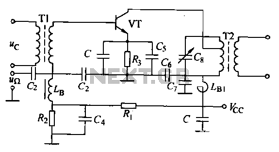
The circuit is designed for small-signal amplitude modulation (AM). Component C functions as a high-frequency bypass capacitor. Transformers T1 and T2 serve as high-frequency transformers, while the LC resonant circuit operates at the carrier frequency with a passband of...

Lithium-based (Li+) batteries are increasingly used in portable devices due to their favorable characteristics. However, they are often in limited supply, leading to long lead times unless a preferred-customer status is established with manufacturers. Consequently, a backup alternative to...