
Transformerless PSU
This circuit functions as a low-power AC to DC power supply that utilizes capacitive reactance for voltage regulation. The circuit is designed to deliver a maximum output current of approximately 20mA at a regulated output voltage of 12V. The use of capacitive reactance minimizes heat generation compared to traditional resistive voltage drop methods, making it efficient for applications that require low power consumption.
The circuit operates by drawing approximately 30mA from the AC mains, which is a crucial aspect to consider during design to ensure proper component ratings and safety measures. To enhance safety, it is recommended to incorporate a fuse or a fusible resistor in the circuit. This precaution helps protect against overcurrent conditions that could lead to component failure or fire hazards.
The output stage of the circuit is designed to interface with devices such as timers, light-operated switches, or temperature controllers. The inclusion of an optical isolator is essential for ensuring safe and reliable operation, as it provides electrical isolation between the high-voltage AC side and the low-voltage DC output side. This isolation is critical in preventing damage to sensitive components and ensuring user safety.
In scenarios where a relay is necessary for switching applications, it is advised to select a relay with a mains voltage coil. The optical isolator should be used to control the relay coil, providing the necessary isolation and protection.
The capacitor C1, which is specified as a suppressor type, is intended to be connected directly across the incoming AC mains supply. This capacitor plays a vital role in filtering out high-frequency noise and transient voltages, thereby improving the overall stability and performance of the circuit. It is typically encapsulated to ensure safety and reliability under operational conditions.
Overall, this circuit design offers a compact and efficient solution for low-power applications, leveraging capacitive reactance and optical isolation to ensure safety and performance.This circuit will supply up to about 20ma at 12 volts. It uses capacitive reactance instead of resistance; and it doesn`t generate very much heat.The circuit draws about 30ma AC. Always use a fuse and/or a fusible resistor to be on the safe side. The values given are only a guide. There should be more than enough power available for timers, light operated switches, temperature controllers etc, provided that you use an optical isolator as your circuit`s output device.
If a relay is unavoidable, use one with a mains voltage coil and switch the coil using the optical isolator.C1 should be of the `suppressor type`; made to be connected directly across the incoming Mains Supply. They are generally covered with th 🔗 External reference
Related Circuits
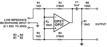
A simple but effective fixed gain transformerless microphone preamplifier circuit diagram is shown in the picture below. The circuit amplifies differential signals from low impedance microphones by 50 dB and has an input impedance of 2 kOhms. The OP27/37...
Connecting a condenser capsule to the grid of a tube amplifier to build a tube microphone. This section discusses how to connect a capsule with two diaphragms to achieve a multi-pattern microphone. First, the different pickup patterns are examined:...
The circuit will work without the extra components, but for reverse polarity protection a 1N5400 diode is provided at the input, extra smoothing being provided by C1. The output stage includes C2 for extra filtering, if powering a logic...
This power supply utilizes a single 7812 IC voltage regulator along with multiple external pass transistors, enabling it to deliver output load currents of up to 30 amps. The circuit design incorporates a 7812 linear voltage regulator, which is...
The 5 volt regulated power supply for TTL and 74LS series integrated circuits has to be very precise and tolerant of voltage transients. These ICs are easily damaged by short voltage spikes. A fuse will blow when its current...
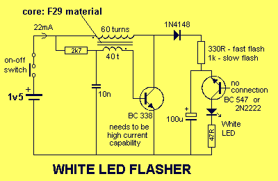
This circuit is very similar to a Joule Thief, but it utilizes two transistors, does not include a transformer core, and employs only one inductor. The described circuit operates on principles akin to those of a Joule Thief, which is...