
High voltage astable multivibrator problem

The design of a high-voltage oscillator capable of operating at 200V and generating a frequency of 1 kHz requires careful consideration of component selection and circuit topology to ensure reliability and efficiency. A typical approach may involve using a feedback oscillator configuration, such as a relaxation oscillator or a Colpitts oscillator, which can provide the desired frequency with minimal current draw.
The oscillator can be constructed using a combination of active and passive components. A suitable choice for the active component could be a high-voltage operational amplifier or a transistor that can handle the 200V supply. The feedback network would typically consist of resistors and capacitors, which determine the oscillation frequency. For a 1 kHz output, the values of these components must be calculated using the formula specific to the chosen oscillator type.
For instance, in a relaxation oscillator, a capacitor will charge and discharge through a resistor, and the time constants involved will directly influence the oscillation frequency. Careful selection of the capacitor's value and the resistor's resistance is crucial to achieving the desired frequency while keeping the current consumption low.
It is also essential to incorporate protective elements such as diodes to safeguard the circuit from voltage spikes and ensure stable operation. Additionally, the layout of the circuit should minimize parasitic capacitance and inductance, which could affect the oscillator's performance.
Testing the oscillator under various load conditions will provide insights into its stability and efficiency. Adjustments to component values may be necessary to optimize performance and ensure that the oscillator meets the specified requirements for frequency and current drain.Hello. I`m trying to make an oscillator that would run from 200V range, providing about 1 kHz with minimal current drain. I started with making a test .. 🔗 External reference
Related Circuits
If you have ever wanted a high-voltage generator to create impressive lightning effects, conduct Kirlian photography experiments, or experiment with neon lights, this project is ideal. It describes a laboratory pulse generator utilizing an auto-ignition coil, capable of delivering...
The following circuit illustrates a low voltage power supply (PSU) for Nixie tubes utilizing a 555 Timer integrated circuit (IC). The coil used in this schematic is purchased from a store. The described circuit operates as a low voltage power...
The timer is utilized in a conventional setup, with the exception that the timing resistor has been substituted with a current source derived from the operational amplifier DA1 (741). This modification enables the achievement of excellent linearity, exceeding 3%....
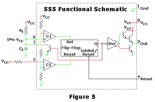
This is one of the most basic 555 circuits. This circuit is part of the chip's datasheet, complete with the math needed to design to specification, and is one of the reasons a 555 is referred to as a...
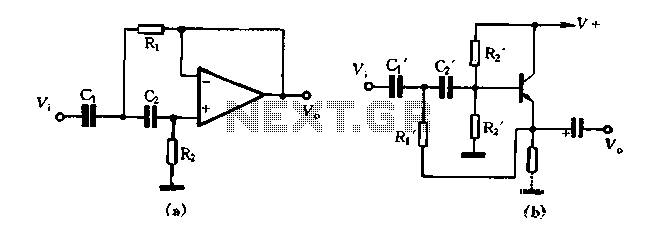
Figure 1-102 illustrates a high-pass filter in part (A). If C1 and C2 are taken as equal and R1 is set to 1/2, then the crossover frequency is given by fH = 1/(2√(2R1C1)). In part (B), if C1 and...
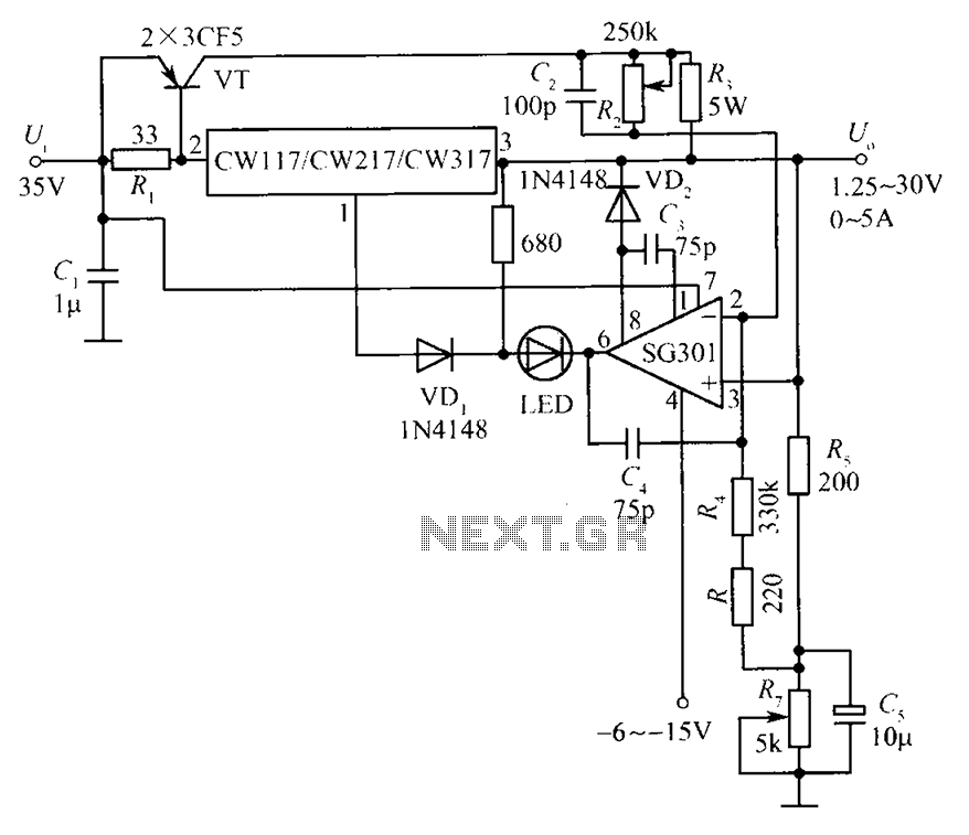
This document presents a diagram of a constant voltage/current power supply box. It is composed of three main components: spread current, constant voltage, and constant current. The design features two 3CF5 power transistors arranged in parallel, functioning as an...