
TRANSISTOR MOTOR CONTROLLER

The circuit utilizes a Darlington pair configuration for Q10, which provides high current gain, making it suitable for driving the LED in opto isolator U5. The opto isolator serves to electrically isolate the control signal from the motor control circuitry, ensuring that any high voltages present in the motor control section do not affect the low-voltage control circuitry. The pulse-width modulation (PWM) technique employed by triac CR1 allows for efficient control of the motor speed by adjusting the effective voltage applied to the motor based on the desired speed.
The operation of the triac is pivotal in this application as it allows for rapid switching and control over the AC waveform, which is necessary for precise motor control. The interaction of the two halves of the triac with the AC waveform enables the system to modulate power effectively. The feedback mechanism involving the disc wedge position ensures that the motor speed is continuously adjusted to maintain the desired operation, providing a responsive control system for the color wheel motor.
Overall, this circuit design exemplifies the integration of modern semiconductor devices with traditional components to enhance performance and reliability in motor control applications. The careful consideration of component interactions and feedback loops is essential for achieving optimal functionality in the system.Despite the high impedance of its inputs, Darlington Q10 develops enough current to drive an LED. The inverted output of Q10 drives opto U5`s internal LED. Opto U5 couples to motor-control triac CR1. Motor Voltage Control Triac CR1. Triac CR1 is a pulse-width modulator. CR1 connects in series with the color wheel motor. The triac circuit replaces V6, a 6BL7 dual triode tube in the original Col-R-Tel circuit. The triac also replaces T3, the Col-R-Tel motor control transformer. The triac gate voltage varies with signals from Q10. The triac output voltage varies with the gate voltage and the line AC. Like the tube in the original Col-R-Tel circuit, the triac has two halves. Each half of the triac is an SCR that interacts with one alternation of the power AC waveform. As triac CR1`s input voltage varies, the triac`s resistance changes. This resistance change increases or decreases the voltage drop across the motor. If the disc wedge is early, then the motor speed is too fast. The CR1 input voltage is low. Triac CR1 increases its resistance and reduces current flow to the motor. The motor slows down. If disc wedge is late, then the motor speed is too slow. The CR1 input voltage is high. Triac CR1 decreases its resistance and increases current flow to the motor. The motor speeds up. 🔗 External reference
Related Circuits
This simple circuit has helped me out on many occasions. It is able to check transistors, in the circuit, down to 40 ohms across the collector-base or base-emitter junctions. It can also check the output power transistors on amplifier...
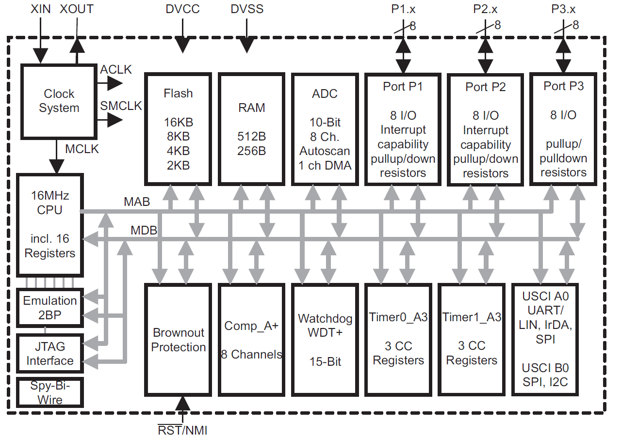
This module provides an overview of the MSP430 microcontroller, instructions on how to read its data sheet, and guidance on selecting the appropriate model for various applications. It is part of a textbook aimed at helping seniors choose Texas...

The purpose of this circuit is to maintain a permanent magnet DC motor at a constant speed, which is set externally. This is achieved by monitoring the current flowing through and the voltage across the motor's brushes. The schematic for...
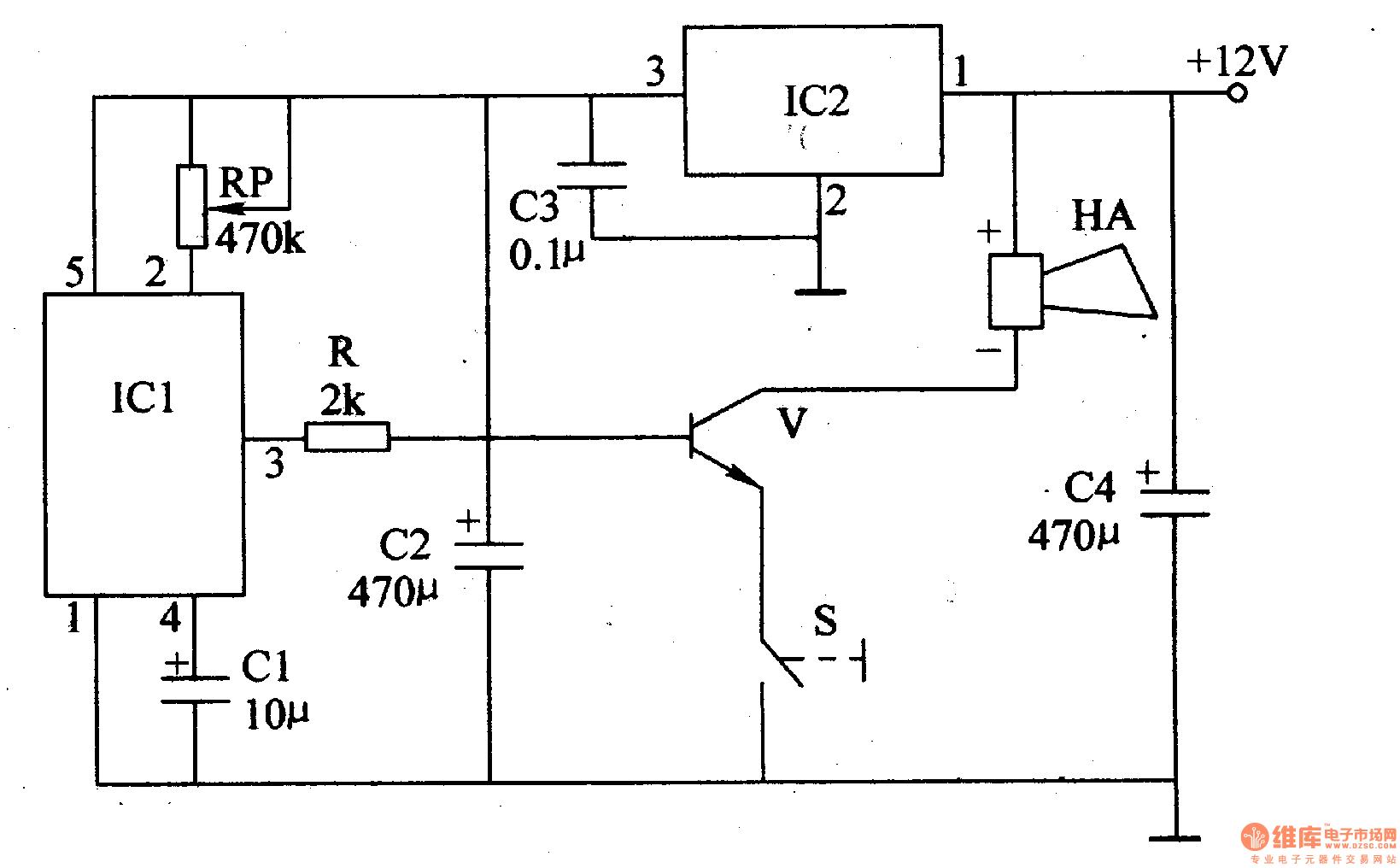
The motorcycle anti-theft alarm described in this article utilizes a proprietary displacement sensor. It is characterized by high sensitivity, good reliability, a low false alarm rate, and ease of construction. The principle of the circuit involves an integrated vibration...
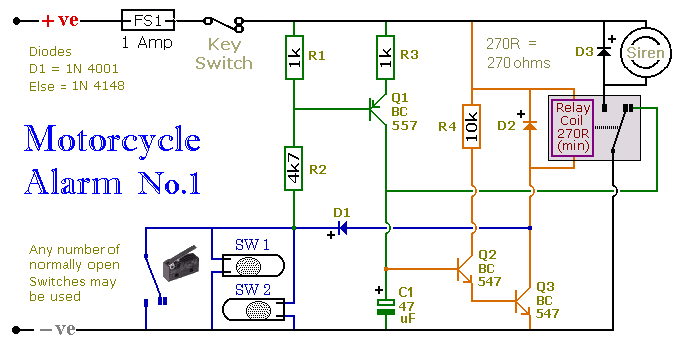
This circuit includes a timed output and an automatic reset feature. It can be manually operated using a key switch or a concealed switch. By incorporating an external relay, the circuit will automatically engage or immobilize the machine each...

The schematic for controlling the motors is divided into three main sections, each serving a distinct function. The primary components featured in the schematic include the PIC 18F252 microcontroller, the SN754410 motor driver, and 2N2222 transistors. At the top...