
Robot Motor Control Schematic

The motor control schematic is designed to facilitate the operation of DC motors using a microcontroller-based system. The PIC 18F252 serves as the central processing unit, executing control algorithms that dictate motor behavior based on input conditions. The 40 MHz crystal oscillator ensures stable timing for PWM generation, which is crucial for speed and direction control of the motors.
The SN754410 motor driver IC is a critical component in this design, capable of driving two DC motors independently. Its H-bridge configuration allows for bidirectional control, enabling the motors to rotate in both clockwise and counterclockwise directions. The differential PWM signals generated by the PIC are essential for controlling the speed and direction of the motors. By modulating the duty cycle of these PWM signals, the effective voltage applied to the motors can be adjusted, thereby controlling their speed.
The inclusion of the 2N2222 transistors for PWM signal inversion is a strategic choice that ensures the motor driver receives the necessary signals in the correct format. The transistors act as switches that invert the PWM signals, creating the required positive and negative outputs for the motor controller. This configuration is vital for achieving precise control over the motors, as it allows for rapid switching between the high and low states of the PWM signals.
In summary, this motor control schematic effectively integrates a microcontroller, motor driver, and signal inversion circuitry to provide a robust solution for controlling DC motors. The design emphasizes the importance of differential PWM signals, ensuring that the motors can be operated efficiently and reliably under various conditions.The schematic for controlling the motors is split up into three main parts, with each part having a unique functionality. The main parts used and seen in the schematic below are the 18F252, SN754410 and 2N2222 Transistors. Seen at the very top, the microcontroller circuit consists of the PIC 18F252, its 40 MHz crystal, a few LEDs, the enable l
ines going to the motor controller and the PWM signals going to the PWM inversion circuit and the motor controller. Two transistors ( 2n2222 ) are used to invert the two PWM signals that are travelling to the motor controller.
This is done because the motor controller needs to have both the `positive` PWM signal and the `negative` PWM signal in what is called a differential pair. The motor controller cannot control our DC motors without both the positive and negative PWM signals.
The main part used for the motor control circuit is the SN754410. This is a quadrule half h-bridge motor controller IC. To use this motor controller, you must input a differential PWM signal, provide power and ground and enable the bank to start-up your motors. The control signals that will tell the motor controller to do all this will be sent from the PIC. 🔗 External reference
Related Circuits
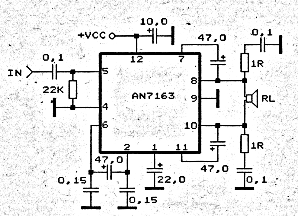
This 5.1 surround amplifier circuit schematic utilizes the IC AN7168 as the primary component. The circuit requires a minimum voltage of 12V and a maximum voltage of 24V, with a recommendation of 12V due to the voltage ratings of...
If EAGLE is not available, a full working version can be downloaded from CadSoftUSA. A zip file containing the EAGLE schematics is provided. The EAGLE software is a widely used electronic design automation (EDA) tool that facilitates the creation of...
This is a circuit to use a standard, low quality opto isolator to transfer an analogue signal with reasonable linearity and without complicated feedback loops to monitor and linearise it. The circuit was designed to interface a mains driven...

Controlling devices using switches is common. Over the past few decades, remote control switches such as infrared remote control switches, wireless remote control switches, and light-activated switches have gained popularity. However, these technologies have their limitations. Laser beams can...

The board can now be tested. Set the DIP switch to Switch1 ON, Switch2 OFF (15-second delay), Switch3 ON, and Switch4 OFF (4 rings to activate half for switching ON). To switch ON relay 1 (connected to RB0 of...
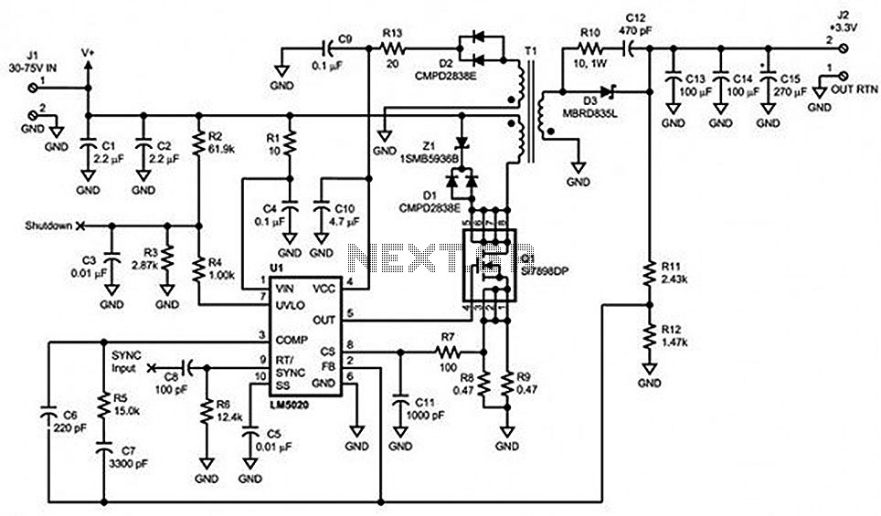
Locate sections such as the LM5020 connection diagram and pin descriptions, the functional block diagram of the device, the line under voltage lockout (UVLO) circuit, an internal high-gain error amplifier, a cycle-by-cycle overcurrent protection function, the setting of the...