
Trip Coil Of Circuit Breaker
The described circuit involves a trip unit functioning in conjunction with a current-limiting polymer element and circuit breaker contacts. The trip unit operates effectively as a shunt resistance, allowing for accurate monitoring and response to overcurrent situations. When the polymer element reaches its high resistive state, it energizes the trip unit, signaling the circuit breaker to actuate.
In the context of the relay operation, the current transformer plays a critical role in safeguarding the circuit. By being connected in series with the line to be protected, it continuously monitors the line current. Under normal conditions, the relay remains open. However, when a fault occurs, the current spikes significantly. The current transformer responds by generating a proportional secondary current, which activates the relay coil.
The relay contacts, once closed due to the fault current, complete the trip circuit of the circuit breaker. This circuit includes a trip coil and a battery, ensuring that the trip mechanism can operate independently of the main power supply. The ability to function with both AC and DC power sources enhances the versatility of the circuit design.
Once the trip coil is energized, it initiates the opening mechanism of the circuit breaker, effectively disconnecting the faulty section from the operational circuit. This disconnection is crucial to prevent damage to the system and ensure safety. The overall design emphasizes reliability and responsiveness, making it suitable for various applications where protection against overcurrent is essential.A trip unit is electrically connected in parallel with a current limiting polymer element in series with circuit breaker contacts to function as a shunt resistance for the polymer element. It becomes energized by transition of the polymer element to its high resistive state for tripping the breaker contacts.
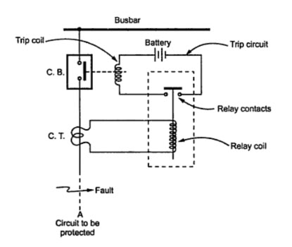
The solenoid may be particularly wound w ith a resistive wire. Here a simplified circuit of a typical relay is given. Basically the relay circuit is a three phase circuit and the contact circuit of relays is very much complicated. This diagram is of single phase simplified circuit to explain the basic action of a relay. Let part A is the circuit to be protected. The current transformer(C. T. ) is connected with its primary winding in series with the line to be protected. The secondary winding of the current transformer is connected in series with the relay coil. The relay contacts are the part of a trip circuit of a circuit breaker. The trip circuit consists of a trip coil and a battery, in addition to relay contacts. The trip circuit can operate on a. c. or d. c. If the fault occurs, Then current through the line connected to A increases to a very high value. Then the current transformer senses this current. Accordingly its secondary current increases which is nothing but the current through a relay coil. Thus the relay contacts get closed mechanically under the influence of such a high fault current. Thus the trip circuit of a circuit breaker gets closed and current starts flowing from battery, through trip coil, in a trip circuit.
Thus the trip coil of a circuit breaker gets energized. This activates the circuit breaker opening mechanism, making the circuit breaker open. This isolates the faulty part from rest of the healthy system. 🔗 External reference
Related Circuits
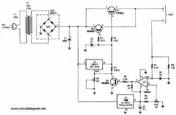
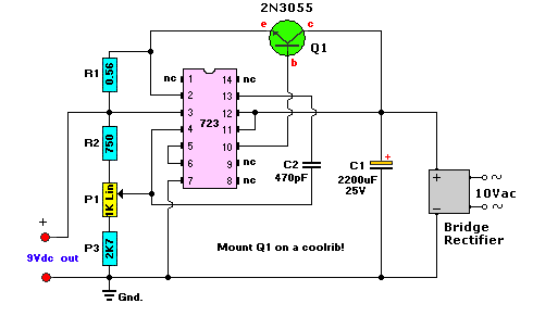
This battery charger circuit is regulated and adjustable, enabling it to charge most NiCAD batteries. It can accommodate both single cells and multiple battery cells connected in series or parallel. The maximum voltage of the batteries should not exceed...
The output frequency can be altered based on the division ratio of the comparison frequency in the 10 kHz unit, with the division ratio set to 1024 in this circuit. Given that the amateur radio bandwidth in Japan is...
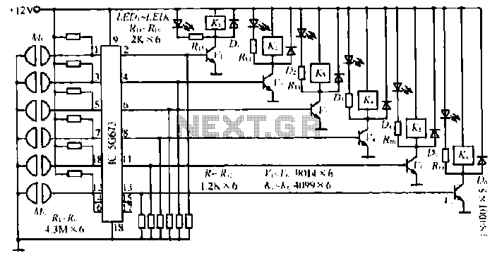
A, B, and C are used for a high-power split-phase system. The A + B' C' arrangement serves as a phase line for a range generator. The A-A' indole path string includes two 220V / 15W bulbs, which are...
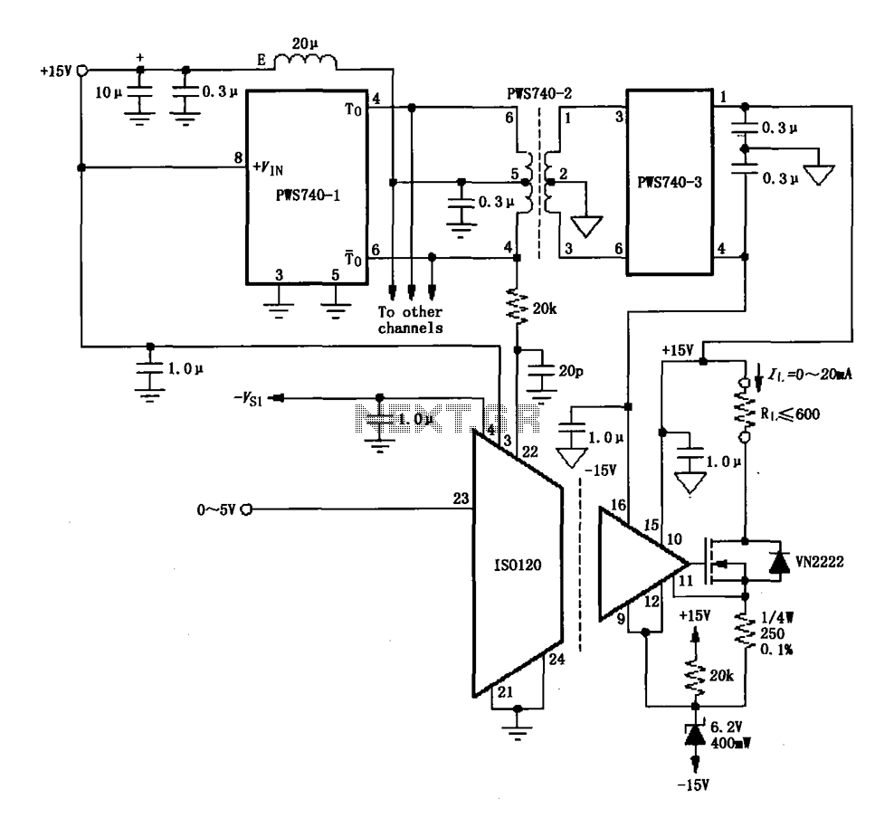
An eight-channel isolation circuit is constructed using the ISO120 and PWS740 components, designed for a 0 to 20 mA current loop. The figure illustrates only one channel, where the circuit converts a 0 to 5V input voltage into a...
This AC to DC power supply can output 5A in continuous operation and 12A peak current. This type of DC power supply uses a PCB, allowing for two case types. The described AC to DC power supply is designed to...
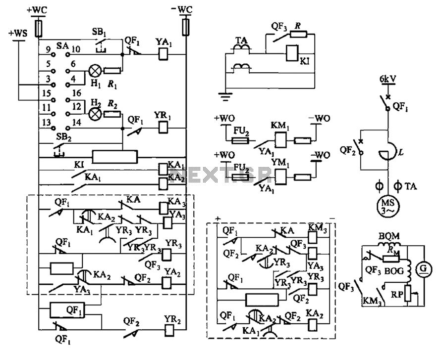
The circuit depicted in Figure 3-189 includes various components such as switch SA, closing button SBi, trip button SBz, de-excitation switch Yaa, and off trip coil YR3. The excitation switch contacts are represented by QF3, which serves as a...