
Adjustable Regulated Battery Charger circuit diagram

The described battery charger circuit is designed for versatility in charging NiCAD batteries, accommodating various configurations and ensuring safe operation within the specified voltage limits. The use of power transistors Q1 and Q2 as series regulators allows for efficient control of both the output voltage and the charging current. The LM-317 voltage regulator serves as a crucial component in providing a stable drive signal, ensuring that the transistors operate effectively under varying load conditions.
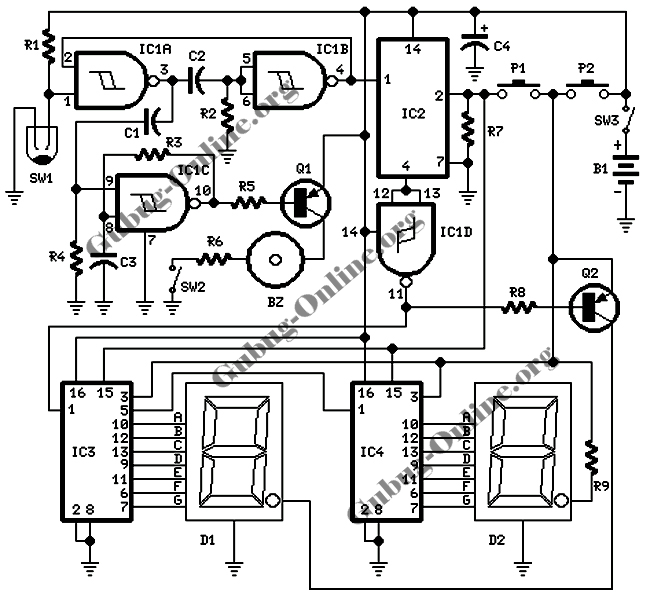
The potentiometer R9 is integral to setting the desired output voltage level, allowing users to adjust the charging voltage according to the specific requirements of the battery being charged. The current sampling resistor R8 plays a vital role in monitoring the charging current; its low resistance value ensures minimal power loss while providing an accurate voltage drop that corresponds to the charging current. This voltage drop is vital for the feedback mechanism that regulates the charging process.
Comparator U3 is essential for maintaining the desired charging current. It compares the voltage across R8 with the reference voltage set by variable resistor R10. As the battery charges and its voltage increases, the charging current decreases, which is reflected in the voltage across R8. This feedback mechanism allows for precise control over the charging process, preventing overcharging and extending the life of the battery.
The circuit's design emphasizes safety and efficiency, making it suitable for various applications where NiCAD batteries are used. By ensuring that the maximum voltage is capped at 18V, the circuit protects the batteries from damage due to overvoltage conditions. Overall, this battery charger circuit represents a practical solution for charging NiCAD batteries with adjustable parameters and reliable regulation.This battery chargercircuitis regulated and adjustable to make this circuit able to charge the mosto NiCAD battery. This circuit will work for single cell or multi battery cell which connected with series/parallel connection.
The maximum voltage of the batteries should be 18V maximum. Power transistors Q1 and Q2 are connected as series regulators to control the battery charger s output voltage and charge-current rate. An LM-317 adjustable voltage regulator supplies the drive signal to the bases of power transistor Q1 and Q2. Potensiometer R9 sets the output-voltage level. A current sampling resistor, R8 (a 0. 1 ohm/5W unit), is connected between the negative output lead and circuit ground. For each amp of charging current that flows through R8, a 100mV output is developed across it. The voltage developed across R8 is fed to one input of comparator U3. The other input of the comparator is connected to variable resistor R10. As the charging voltage across the battery begins to drop, the current through R8 decrease. Then the voltage feeding pin 5 of U3 decreases, and the comparator output follows, turning Q3 back off, which completes the signal`s circular path to regulate the battery`s charging current.
We aim to transmit more information by carrying articles. Please send us an E-mail to wanghuali@hqew. net within 15 days if we are involved in the problems of article content, copyright or other problems. We will delete it soon. 🔗 External reference
Related Circuits
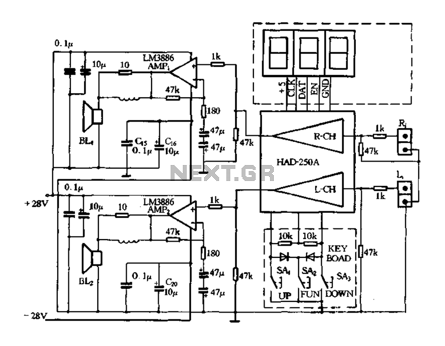
Figure 4-20 illustrates the HAD250A-3 active speakers and amplifier circuit, which features the LM3886 integrated amplifier. This circuit operates with a 25V power supply and delivers an output power of up to 50W per channel, making it suitable for...
This is a simple circuit diagram for a 150W power amplifier. The circuit can be constructed without a printed circuit board (PCB). The power output ranges from 100W to 150W, depending on the power supply and the Darlington transistors...
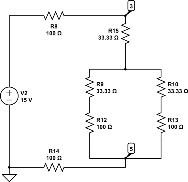
The Delta configuration of resistors R2, R3, and R4 is converted to a Wye (Y) configuration. This conversion is necessary because a voltage divider is typically employed in series circuits. The aim is to determine the total resistance in...
The instrument used to measure battery capacity. The battery may be charged to any current in the range 0-3 A. The load current may be constant, may change over time or even break off completely. Unloading stops when the...

This simple circuit can be used to sense the distance between the rear bumper of a car and any obstacle behind it. The distance is indicated by the combination of LEDs (D5 to D7) that illuminate: at 25 cm,...
This design features a signal logic tester that utilizes a common cathode seven-segment display. The display indicates a logic level "1" (represented by an "H" on the display) or a logic level "0" (represented by an "L" on the...