
Triple Power Supply
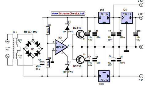
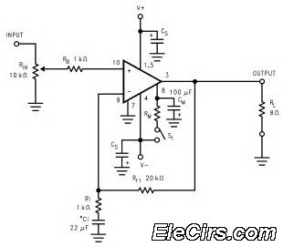
Miniature transformers are compact devices commonly utilized in various electronic applications, particularly in power supply circuits. These transformers are designed to convert alternating current (AC) voltage from the primary side to one or two lower voltages on the secondary side. The ability to provide both positive and negative voltage outputs makes these transformers particularly valuable in applications such as operational amplifier circuits, analog signal processing, and other electronic systems requiring dual supply voltages.
The construction of miniature transformers usually involves a core made from magnetic materials, which enhances the efficiency of magnetic coupling between the primary and secondary windings. The number of turns in each winding determines the voltage transformation ratio, which is critical for achieving the desired output voltages. It is essential to select a transformer with appropriate ratings for current and voltage to ensure reliable operation and prevent overheating.
In practical applications, these transformers are often used in conjunction with rectifiers and voltage regulators to produce stable DC voltages from the AC output. The rectification process typically involves using diodes to convert AC to pulsating DC, followed by filtering capacitors to smooth the output. The resulting DC voltage can then be further regulated to meet specific voltage requirements.
Miniature transformers are widely available and cost-effective, making them an ideal choice for hobbyists and professionals alike when designing compact electronic circuits that require dual power supplies. Their versatility and ease of integration into various designs contribute to their popularity in the electronics industry.Inexpensive miniature transformers normally provide one or two secondary voltages, which is sufficient for generating a set of positive and negative suppl.. 🔗 External reference
Related Circuits
Most devices used in amplifier output stages exhibit significant non-linearity, with transistors (both bipolar and FET) being particularly problematic. These components are almost always employed within a global feedback loop to mitigate their non-linear characteristics. Similarly, tetrode and pentode...
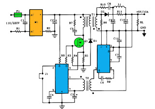
The schematic above illustrates a 10A power supply with a 5V output and a power rating of 50W. It operates as a flyback converter in continuous mode. The circuit includes both primary and secondary side controllers, providing comprehensive protection...
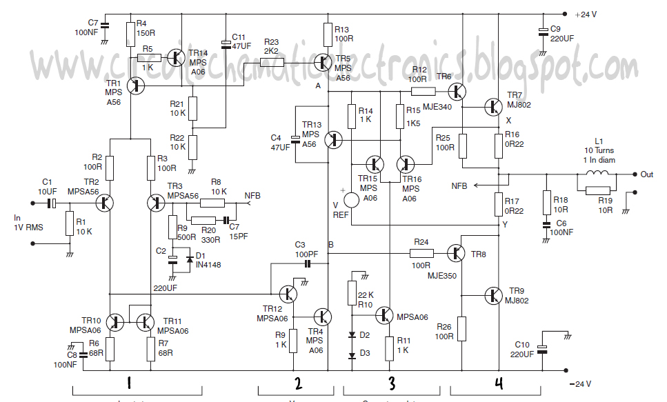
This design schematic represents a Class A power amplifier. It closely matches the operating parameters of Class B to facilitate comparison, particularly with a negative feedback (NFB) factor of 30dB at 20 kHz. The front end is similar to...
The LM3886 high-performance audio power amplifier circuit schematic is a crucial component in sound reproduction within audio systems. This audio power amplifier utilizes the LM3886 integrated circuit to enhance sound quality and output. The LM3886 is a high-performance audio power...
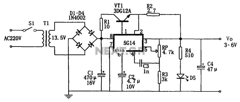
As shown in the figures, this is a practical adjustable power supply. It utilizes an integrated voltage regulator (5G14) in conjunction with a 3DG12A transistor for current spreading, providing an output voltage range of 3 to 6V. The rated...
The output voltage can be increased easily by placing a resistor in parallel with Ra until it reaches precisely 5.0 V. Switches S1 and S2 are preferably SPDT types with a center position, but three-way rotary switches can also...