
True RMS Watt Meter
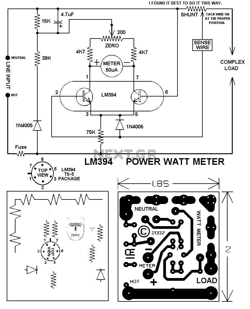
The watt meter circuit described is designed to measure electrical power in a specific range, accommodating home circuit parameters. The core component of the design is a shunt resistor, which is crucial for measuring current. The selection of a 0.001 Ohm shunt resistor allows for accurate measurement of current flowing through the circuit, which can be calculated using Ohm's law. This low resistance value minimizes the impact on the circuit being measured while still providing sufficient voltage drop for measurement.
The design features a shunt configured in an inverted V shape, which is beneficial for spatial efficiency and thermal management. The five loops of wire increase the effective surface area, allowing for better heat dissipation during operation, which is particularly important at higher power levels. The choice of #16 AWG wire is suitable for handling the current without excessive heating, but it is essential to verify the wire gauge against the expected load to ensure safety and reliability.
The output of the shunt is typically connected to an analog or digital voltmeter, which interprets the voltage drop across the shunt and converts it into a power reading. This conversion involves multiplying the measured voltage by the current flowing through the circuit, which can be calculated based on the known resistance of the shunt. The design allows for a maximum measurement of 1500 Watts, aligning with the common household circuit breaker ratings.
To enhance the accuracy of the watt meter, it is recommended to calibrate the device against known power sources. This ensures that the readings reflect true power consumption, accounting for any potential discrepancies in component tolerances or environmental factors. Overall, this circuit provides a practical solution for monitoring power usage in residential applications, offering insights into energy consumption and facilitating better energy management.This circuit will give you a good, Accurate Watt Meter that can measure various power levels. In the Origional Article the Shunt was a .001 Ohm Copper Shunt giving a 1000 Watt Scale. However, because Most Circuit Breakers in homes are 15 Amps, I made my unit to have a range of Zero to 1500 Watts. The Shunt on my unit is comprised of 5 small LOOPS in a Single piece of wire in an Inverted V Shape or an " _n_n_n_n_n_ " Shape, going from pad to pad. I used a #16 AWG wire, but you need to determine wire size and lengths based on the wattage r 🔗 External reference
Related Circuits
This complete high quality, low noise mono audio power amplifier is based around the Hybrid Integrated Circuit STK4050 manufactured by Sanyo. The circuit incorporates volume and has a maximum music output power of 200W. The circuit incorporates an on...
Home-built NMR spectrometer, illustrating the construction and circuitry. Demonstrates 90-degree and 180-degree pulse sequences, as well as the generation of FIDs and spin echoes at 18 MHz. The home-built NMR (Nuclear Magnetic Resonance) spectrometer is an intricate device designed for...
The RF signal is divided into two signals that are shifted 90 degrees out of phase (one at plus 45 degrees and one at minus 45 degrees). Both signals are then mixed to audio frequencies. The two audio signals...
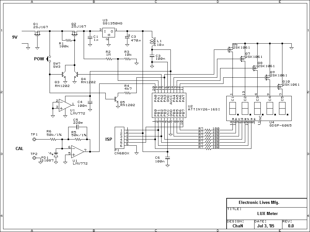
Photo diode outputs light current that is well proportional to input light power when it is used in short mode. In this lux meter, the output current is converted to voltage with an I-V converter, it is captured by...
This inductance meter serves as an adapter for a digital voltmeter (DVM), enabling the voltmeter to measure the value of inductors. The inductance meter is particularly useful in designing switch mode power supplies, as it often requires hand-winding coils...
This digital thermometer indicates the temperature measured with an NTC using 7 LEDs. The circuit works using an opamp, the well-known 741, which amplifies the voltage difference between its plus and minus input. This amplification (sensitivity) can be set...