
LED Digital Thermometer schematic

The digital thermometer circuit utilizes an NTC (Negative Temperature Coefficient) thermistor for temperature measurement, which exhibits a decrease in resistance as temperature increases. The circuit is designed around the operational amplifier (op-amp) IC 741, which is configured to amplify the voltage difference between its non-inverting and inverting inputs.
The sensitivity of the op-amp can be adjusted using potentiometer P2, allowing for fine-tuning of the output response based on the temperature variations detected by the NTC thermistor (R1). The adjustment of P1, in conjunction with R1, forms a voltage divider that sets the reference voltage for the op-amp.
The output from the op-amp (IC1) is used to control a series of transistors (T1 - T7, which are BC557B PNP transistors). As the output voltage from the op-amp decreases, it allows more transistors to turn on, which in turn lights up more LEDs (D7 - D13). The number of LEDs illuminated corresponds to the temperature reading, providing a visual indication of the measured temperature.
Resistors R2 and R3 are used to set the gain of the op-amp, while R4 provides additional stability to the circuit. Resistors R5 through R13 serve as current-limiting components for the LEDs, ensuring that they operate within safe current levels. R14 is used to limit the base current to the transistors, and resistors R15 through R21 are likely used as pull-down resistors or for biasing purposes.
Capacitor C1 (100 nF) is added to filter out noise and stabilize the power supply to the op-amp, ensuring reliable operation. Diodes D1 - D6 (1N4148) may be employed for protection against reverse polarity or to prevent back EMF from affecting the circuit.
In summary, this digital thermometer circuit is efficient and straightforward, providing a clear visual representation of temperature changes through the use of LEDs, while maintaining the ability to adjust sensitivity and reference voltage for accurate measurements.This digital thermometer indicates the temperature measured with an NTC using 7 LEDs. The circuit works using an opamp, the well-known 741, which amplifies the voltage difference between its plus and minus input. This amplification (sensitivity) can be set using P2. The bridge of P1 and R1 can be adjusted using P1. The output voltage of IC1 determines how many LEDs will light up. As the output voltage of the opamp decreases, more transistors will conduct and thus more LEDs will light up.
Parts: R1 = 47 kOhm NTC R2, R3 = 2.2 kOhm R4 = 1 kOhm R5 - R13 = 10 kOhm R14 = 33 kOhm R15 - R21 = 270 ? P1, P2 = 220 kOhm C1 = 100 nF D1 - D6 = 1N4148 D7 - D13 = LED T1 - T7 = BC557B IC1 = 741 🔗 External reference
Related Circuits
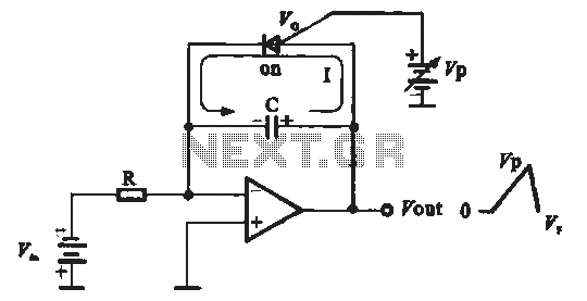
A sawtooth voltage-controlled oscillator operates by first generating a negative potential maximum at the output of the comparator. This output is then fed to the inverting input terminal through resistor R1, which is part of the relaxation oscillator. The...

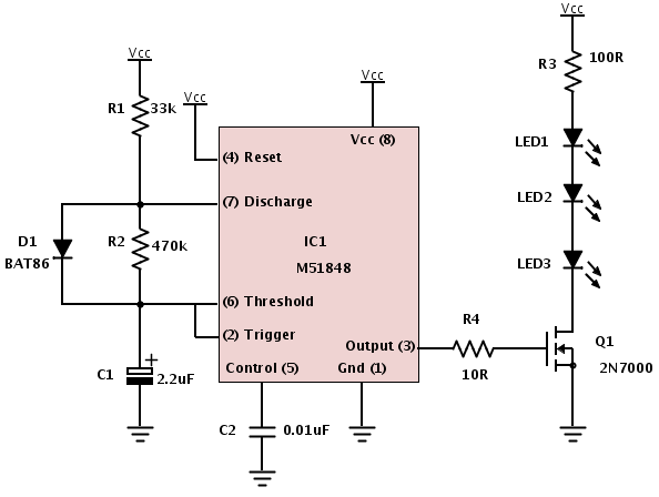
This 40 kHz crystal-controlled oscillator circuit drives an infrared LED with powerful 40 mA pulses. The circuit operates at a frequency of 40 kHz, determined by the crystal oscillator, which provides stable frequency output essential for applications requiring precise timing....
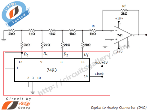
A Digital to Analog Converter (DAC) is utilized to produce an analog voltage that corresponds to input digital data. Binary data can be transformed into its analog equivalent using an R-2R ladder network combined with a summing amplifier, which...
Build an interface board to connect scientific equipment, specifically a pair of photovoltaic tubes, to a personal computer for acquiring measurement results. The signal properties include two channels with a common ground, a one-second acquisition time, and a maximum...
A common issue encountered is that individuals possess a schematic, also known as a circuit diagram, that they wish to construct. However, they discover that there are... Building a circuit from a schematic requires a clear understanding of the components...
A mute switch for the Etherwave that adds a "mute status" light, which also functions as a power-on indicator. The schematic is provided. It is recommended to explore the additional resources available on Art's website. The mute switch circuit for...