
Trying to build an Ambilight

The Ambilight system utilizes a combination of LED lights and microcontrollers to create an immersive lighting experience that responds to on-screen content. The ATtiny44 microcontroller serves as the central processing unit, controlling the LED strips based on the input it receives. The programming of the microcontroller involves writing code that interprets video signals and translates them into color and brightness commands for the LEDs.
The 74HC95 shift register plays a critical role in managing the data flow from the microcontroller to the LED array. When configured for parallel output, it can drive multiple LEDs simultaneously, enhancing the responsiveness of the lighting effects. In contrast, using serial output may simplify wiring but can limit the number of LEDs that can be controlled at once.
To successfully implement the Ambilight system, it is crucial to consider the power requirements of the LED strips, ensuring that the microcontroller and shift registers can handle the current load without overheating. Proper heat dissipation methods should be employed, such as using heatsinks or ensuring adequate airflow around the components.
Additionally, the design should include protective measures such as resistors to limit current and prevent damage to the LEDs and microcontroller. The circuit should be carefully laid out to minimize noise and interference, which could disrupt the operation of the microcontroller and the overall performance of the Ambilight system.
In summary, building an Ambilight system involves a careful selection of components, proper programming of the microcontroller, and an understanding of data transmission methods to achieve a visually stunning and responsive lighting solution.This is a discussion on Trying to build an Ambilight within the Electronics forums, part of the Tech Support Forum category. Hey there, I was recently looking at back lighting lights/LED`s for behind monitors. and I came across a thing called I was recently looking at back lighting lights/LED`s for behind monitors.
and I came across a thing called Ambilight. I saw it and now im thinking I want to build one myself, But I am a novice when it comes to electronics but I do have a friend that is an electrician that will help me along the way. i just need if anyone can make some sense of the drawings and help me really. The ATtiny44 is a micro controller which is a surface mount Quad-Flat-No-Lead package type. This means that the microcontroler pins are soldered on top of the printed circuit board so there is more space to add more components.
The micro controller is programmed in machine code which is written in assembler or C+. You will need the data sheet of the micro-controller to understand what the inputs and outputs of the pins do to program the microcontroller correctly or else you risk shut down or in some cases it goes up in smoke. The 74HC95 are 8 bit registers, registers are called arrays because they have fast memory. Think of it as box that has holds information that comes in one side and leaves the other. The output of the the registers are connected to your LED array, the register can send out the information from the micro controller in different ways.
It could be sent out as parallel or serial. Parallel is when multiple inputs are used. Think of it as train tracks that are going in one direction, but the output of the register could be serial which means only one output is used or vice versa. " What were dealing with is the battle between the future and the past, between the powers that were and the powers that have yet to be.
" - John Perry Barlow 🔗 External reference
Related Circuits
Build a 20 Amp 13.8 Volt Power Supply. There are some electronic applications where it may be necessary to run relatively high current circuits, such as transformers. To construct a 20 Amp, 13.8 Volt power supply, the following components and...
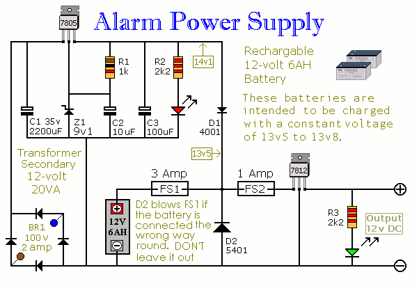
This power supply is designed for the Modular Burglar Alarm but is suitable for various applications. It delivers a 12-volt output with a maximum current of 1 amp. In case of a mains failure, the backup battery activates immediately,...
This guide provides instructions for becoming a radio pirate by creating a low-power FM transmitter to broadcast content on the airwaves. It serves as a follow-up to a recent call for easing restrictions on radio broadcasting in the Maldives....
This is a single transistor pump circuit. It is a straightforward circuit that is quite useful and can serve as a foundational component for designing more complex electronic systems. The single transistor pump circuit utilizes a transistor as the primary...
A stereo valve phono preamplifier has been constructed by a technician. The device requires a power transformer and various components, excluding the valves, which the technician recommends sourcing based on individual needs. Experienced DIY enthusiasts are invited to share...
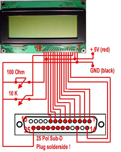
For the wiring of the display, the ribbon cable is first taken and soldered according to the circuit diagram on the 25-pin sub-D (parallel port) plug. The small circuit diagram illustrates the rear side, which is the solder side...