
Build a FM radio transmitter
The construction of a low-power FM transmitter involves several key components and steps that are essential for effective operation. The circuit typically includes a power supply, an oscillator, a modulator, and an antenna. The power supply can be sourced from batteries or a DC power adapter, ensuring a stable voltage for the transmitter's operation.
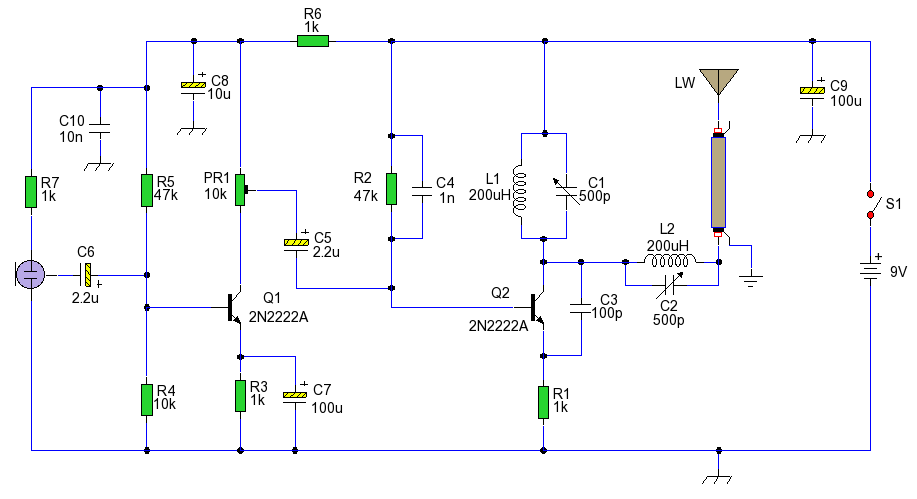
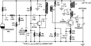
The oscillator is the heart of the transmitter, generating a radio frequency signal. A simple transistor-based oscillator circuit can be employed, utilizing components such as resistors, capacitors, and a transistor to create the necessary oscillation. The frequency of oscillation can be adjusted by varying the values of the capacitors and inductors used in the circuit.
The modulator is responsible for combining the audio signal with the radio frequency signal generated by the oscillator. This can be achieved using a simple audio transformer or by directly coupling the audio signal to the transistor. Care must be taken to ensure that the audio levels are appropriate to avoid distortion during transmission.
The tuning coil, as mentioned, is crucial for adjusting the transmitter to the desired frequency. The number of turns and the spacing of the coil can significantly impact the tuning range and efficiency of the transmitter. It is advisable to experiment with different coil configurations to optimize performance.
Finally, the antenna plays a vital role in radiating the transmitted signal. A simple wire antenna can be used, with its length adjusted to match the desired frequency for optimal transmission range. The antenna should be elevated as much as possible to enhance the broadcast range.
In summary, building a low-power FM transmitter requires a basic understanding of electronics, along with the right components and construction techniques. By following the outlined steps and making necessary adjustments, individuals can successfully create a transmitter capable of broadcasting their content within a limited range, allowing for creative expression in the realm of radio broadcasting.This is a guide to becoming a techno rebel: a guide to becoming a radio pirate and raiding the silent airwaves with your own content. This is a follow up to my recent call for relaxing the grip on radio broadcasting in the Maldives. One of the easiest transmitters to build is a FM transmitter. A basic low power transmitter can be assembled in a fe w hours, using a minimal set of equipment and components and best of all, it can be done without denting the wallet too much. I am going to describe how to build a very low power FM transmitter. Do not expect this to cover the entire country, an atoll or even an island - it surely will not. However, it will be able to transmit around a block (maybe more with a good antenna) which is more than enough to tread into the world of radio and let yourself be heard.
- You need basic familiarity with electronics to undertake this project. If you studied GCE O` level Physics (or A level Physics) then you should be familiar with the basic knowledge to go ahead with the construction. - You can build this using a variety of construction techniques. The preferred method would be using strip board or perf board however point to point wiring would work too.
Have a look here for a quick intro to circuit construction methods. Strip boards ARE available in Male`. - The components given below can be interchanged for a equivalent and values can be approximated. So go ahead and scrounge around broken electronic items for the required components - chances are you will find most of them in broken TVs, Radios and even some toys. The tuning coil used is a length of the insulated copper wire wound around a small pencil about 6 times.
The circuit can be tuned to the broadcast FM range by adjusting the coil appropriately. Turn on a FM radio and set it to the frequency you want this circuit to transmit at. Next, try squashing and/or spacing the coil turns until it is tuned to the desired frequency. The audio can be fed to the transmitter via a tape player, a PC or even an Ipod. All that remains is for you to make your killer radio programs and broadcast it. Have fun! 🔗 External reference
Related Circuits

The integrated circuit (IC) is a multistandard vision and sound intermediate frequency (IF) phase-locked loop (PLL) demodulator that operates without the need for alignment. It supports multiple television standards, including PAL, SECAM, and NTSC, and is capable of handling...
An AM voice transmitter with variable tuning. The antenna circuit is also tuned and transmits via a long wire antenna. It is illegal to transmit on the AM wavebands in most countries; therefore, this circuit is provided for educational...
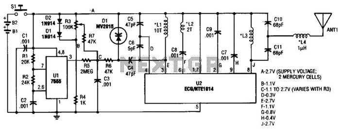
This transmitter can be utilized for multiple applications. An INS8048L microprocessor produces various codes based on keypad inputs. These codes are modulated onto a 40-kHz carrier frequency. Additionally, Q1 drives infrared LEDs LED1 and LED2. The transmitter circuit primarily consists...
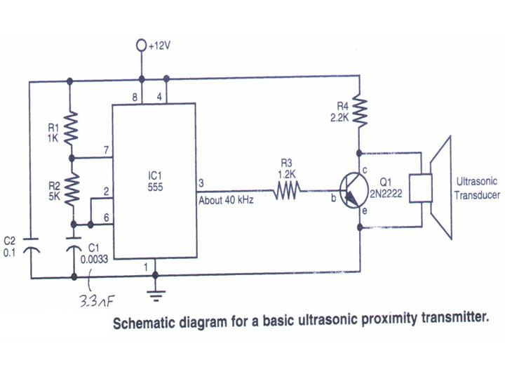
This section provides step-by-step instructions along with images for constructing an Ultrasonic Proximity Transmitter. Due to the simplicity of the circuit, only a schematic for the sensor is presented here. The objective of this tutorial is to assist others...
Clearly indicate on the circuit diagram each type and size of the components. There is a need for assistance in designing a low power FM transmitter circuit, specifically using the BA1404 FM transmitter with a center frequency of 79W...
In the transmitter schematic, a ballast resistor is not depicted because most small laser power supplies are typically equipped with an integrated ballast resistor. However, variations in power supply designs may require the addition of an external resistor. In laser...