
Tube-based Buffer amplifier
The design of a tube-based power buffer presents unique challenges and opportunities for innovation. The approach to using a pentode allows for a significant amount of feedback to be applied, which is essential for minimizing distortion and improving overall performance. The choice of output transformer plays a critical role in the performance characteristics of the buffer. The transformer not only matches impedance but also influences the frequency response and transient response of the system. Careful selection of transformer specifications, including primary impedance and winding ratio, is crucial for optimizing the output impedance and achieving desired performance metrics.
Incorporating robust power supply design is also essential. A well-regulated power supply can provide the necessary voltage swings required for the pentode operation while minimizing noise. The layout of the circuit should consider the placement of components to reduce parasitic capacitance and inductance, which can negatively impact performance. Additionally, the use of high-quality passive components, such as capacitors and resistors, can contribute to lower noise levels and improved fidelity.
The overall design should also include provisions for thermal management, as power tubes can generate significant heat during operation. Adequate ventilation and heat sinking strategies should be employed to ensure the longevity and reliability of the components.
In conclusion, the development of a tube-based power buffer capable of driving loudspeakers directly requires a careful balance of design considerations, including feedback implementation, transformer selection, power supply stability, and thermal management. Through meticulous engineering and component selection, it is possible to create a high-performance tube buffer that meets the demands of modern audio applications.The solid-state, unity-gain power buffer is easy to imagine, as many already exist. But what about corresponding tube equivalents Have they been made Could one be made Actually, super cathode followers (complex-and-augmented cathode followers with a gain of 0. 99) have a long history, with many interesting designs appearing in the 1940s and 1950 s. But a tube power buffer robust enough to drive directly loudspeakers is rare, and with good reason: the impedance mismatch can only be easily addressed with an output transformer. Because of the transformer`s phase shifts, however, the amount of feedback that can be wrapped around a tube amplifier and its output is limited.
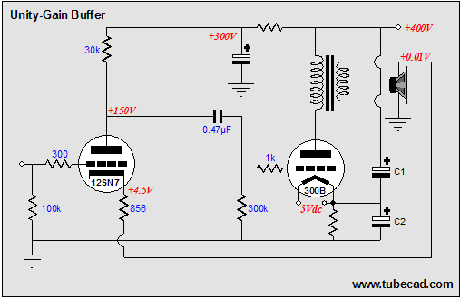
And all buffers use some form of feedback to deliver low distortion and output impedance. Couldn`t an OTL tube-based power buffer be created that would allow much greater amounts of feedback to be used Sure; but it, like all tube OTL amplifiers, will be a beast. In the schematic above, we see a power pentode configured in a simple single-ended topology, with the only interesting twist being the pentode`s cathode direct connection to the transformer`s secondary.
This connection eliminates the pentode functioning as an amplifier, as the cathode follows the grid, thus providing 100% degenerative feedback. This short feedback loop gives the pentode`s output stage a low impedance output that it would otherwise be altogether lacking.
It also lowers the distortion, improves the PSRR, and extends the bandwidth. Actually, the PSRR is fairly good in a pentode-based single ended amplifier, even without the feedback loop, as the pentode`s high rp, unlike the triode`s low rp, makes a poor voltage divider against the output transformer`s primary impedance. In the schematic below, we can see the noise relationships throughout the power buffer. Then we must ask ourselves which pentode to use and how many of them. The KT88/6550 and EL34 are obvious choices, but there are many more pentodes that would work well in this application; for example, the WE350, EL84, 6L6, EL509, KT99 and many others.
With a KT88/6550 configured as pentode, an easy 10W could be had per tube (a triode-connected KT88/6550 would yield only half as many watts). The hard part would be in providing enough clean input voltage swing to drive the pentode to its full output.
Remember, we are returning the output stage`s output to the cathode, so the input drive voltage must exceed the loudspeaker`s voltage by at least the bias voltage used. For example, if the pentode sees a peak output into the loudspeakers of 16V and a -30V bias voltage, then the input signal to the pentode`s grid must be at least 46V to get to a zero cathode-to-grid voltage.
In other words, do not expect your iPod to be able to drive this power buffer directly. (In fact, it is hard to see how any unity-gain buffer with a gain of only 0. 35 can go by that name. ) However, with an Aikido line amplifier that holds a 12AX7 in the input tube position or just about any high-gain tube circuit, it should be possible to drive the pentode to full output, even with the iPod. The output impedance of this amplifier equals the inverse of the pentode`s transconductance divided by the square root of the transformer`s impedance ratio (in other words, the winding ratio).
For example, a 5, 000-ohm primary impedance equals an impedance ratio of 625:1 (625/8) and a winding ratio of 25:1. So when the inverse is taken, a pentode with a transconductance of 10mA/V would equal 100-ohms; and the 100 ohms dived by 25 would equal the output impedance ”namely, 4 ohms, for a damping factor of 2.
If we desire a lower output impedance, then a higher-transconductance pentode or higher winding-ratio transformer could be used. For example, a pentode with twice the transconductance (or two of the same pentodes in parallel) would yield half the output impedance.
Beyond these two measures, there is little that we can do 🔗 External reference
Related Circuits
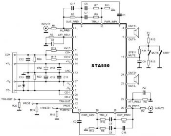
This is a stereo amplifier circuit diagram. The amplifier will produce stereo output channels with a power audio output that can reach up to 70W for each channel. The amplifier is built using the STA550 chip from STMicroelectronics. It...
Inspect the work for potential dry joints, shorts across adjacent tracks, or soldering flux residues, as these often lead to issues. Recheck all external connections to and from the circuit for any mistakes. Ensure that all polarized components are...

A compact, inexpensive and low component count telecom headset can be constructed using two readily available transistors and a few other electronic components. This circuit is very useful for hands-free operation of EPABX and pager communication. Since the circuit...
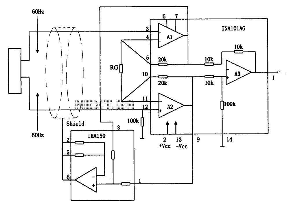
The circuit diagram illustrates a hum elimination instrument amplifier circuit. The amplifier stages A1 and A2 utilize the integrated operational amplifier INA101, followed by stage A3 which employs the INA105. A feedback circuit is incorporated to reduce the power...
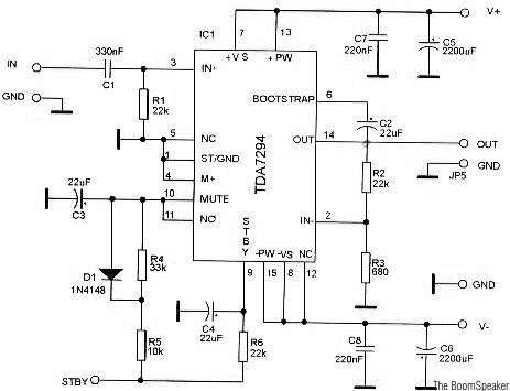
The TDA7294 is a monolithic integrated circuit housed in a Multiwatt15 package, designed to deliver high output power of up to 100W. It is intended for use as an audio Class AB amplifier in high-fidelity applications. The TDA7294 is a...
In recent years, following CD's introduction, vinyl recordings have almost disappeared. Nevertheless, a phono preamplifier is still useful for listening to old vinyl discs from a well-preserved collection. This simple but efficient circuit devised for cheap moving-magnet cartridges can...