
Telephone Headphone amplifier

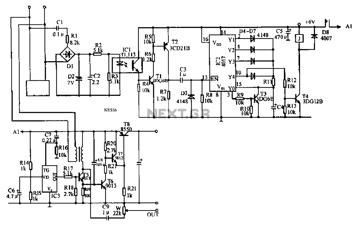
This telecom headset circuit is designed to facilitate hands-free communication, making it suitable for use with EPABX systems and pagers. It employs a minimalistic approach, utilizing only two transistors (T1 and T2), a few resistors, diodes, capacitors, and a microphone, thus ensuring cost-effectiveness and simplicity in construction. The circuit's low current draw allows it to operate in parallel with existing telephone sets without significant power consumption.
The visual ringer circuit is established by resistor R1 and a neon glow lamp, which provides a clear indication of incoming calls. The glow lamp remains off during idle conditions due to insufficient voltage to ionize the neon gas, ensuring that only the ringing signal activates the lamp.
The bridge rectifier, composed of diodes D1 to D4, serves as a polarity protection mechanism, safeguarding the circuit against potential damage from reversed line polarity. Zener diode D5 further enhances protection by clamping the voltage at the output of the rectifier, preventing over-voltage conditions.
Transistor T1, along with resistors R2, R3, and zener diode D6, forms a constant voltage regulator that stabilizes the output voltage at approximately 5 volts, which is essential for the operation of the subsequent stages.
The audio receiving stage is constructed around transistor T2, with additional components like resistors R7, R6, and capacitor C5, which amplify the dial tone and speech signals from the exchange. The output from the collector of T2 is coupled to the dynamic receiver (RT-200) through capacitor C7, ensuring that the amplified audio signals are delivered to the earpiece effectively.
For audio transmission, a condenser microphone is utilized, capturing sound signals that are then coupled to the base of transistor T1 through capacitor C3. The biasing for the microphone is set by resistor R4, which ensures proper operation of the microphone within the circuit.
The amplified audio signals from T1 are subsequently fed back to the telephone lines through the diode bridge, completing the communication loop. The compact design allows for the entire circuit to be implemented on a small printed circuit board (PCB), which can be conveniently housed in a standard-sized headphone, facilitating ease of use and portability. Adjustments to resistor R2 may be necessary for optimal performance under varying line current conditions.A compact, inexpensive and low component count telecom head- set can be constructed using two readily available transistors and a few other electronic components. This circuit is very useful for hands-free operation of EPABX and pager communication. Since the circuit draws very little current, it is ideal for parallel operation with electronic telephone set.
Working of the circuit is simple and straightforward. Resistor R1 and an ordinary neon glow- lamp forms a complete visual ringer circuit. This simple arrangement does not require a DC blocking capacitor because, under idle conditions, the telephone line voltage is insufficient to ionise the neon gas and thus the lamp does not light. Only when the ring signal is being received, it flashes at the ringing rate to indicate an incoming call.
The bridge rectifier using diodes D1 through D4 acts as a polarity guard which protects the electronic circuit from any changes in the telephone line polarity. Zener diode D5 at the output of this bridge rectifier is used for additional circuit protection. Section comprising transistor T1, resistors R2, R3 and zener diode D6 forms a constant voltage regulator that provides a low voltage output of about 5 volts.
Dial tone and speech signals from exchange are coupled to the receiving sound amplifier stage built around transistors T2 and related parts, i.e. resistors R7, R6 and capacitor C5. Amplified signals from collector of transistor T2 are connected to dynamic receiver RT-200 (used as earpiece) via capacitor C7.
A condenser microphone, connected as shown in the circuit, is used as transmitter. Audio signals developed across the microphone are coupled to the base of transistor T1 via capacitor C3. Resistor R4 determines the DC bias required for the microphone. After amplification by transistor T1, the audio signals are coupled to the telephone lines via the diode bridge.
The whole circuit can be wired on a very small PCB and housed in a medium size headphone, as shown in the illustration. For better results at low line currents, value of resistor R2 may be reduced after testing. 🔗 External reference
Related Circuits
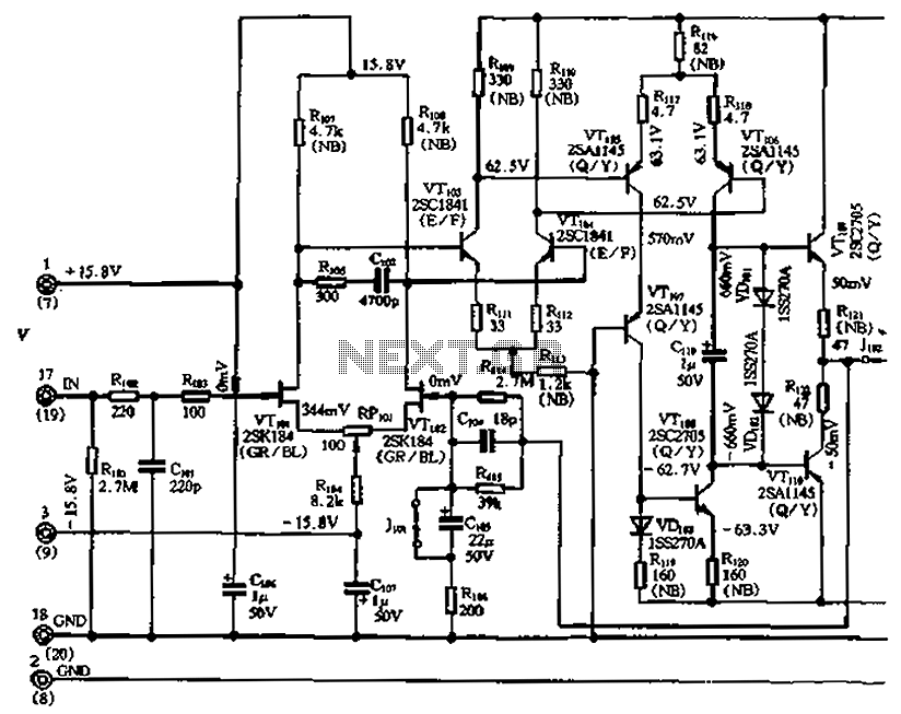
The circuit features a differential input stage that implements differential voltage amplification, forced differential voltage amplification, and a complementary push-pull amplifier output. It includes a bias circuit, a distortion servo circuit, and a protection circuit. The input preamplifier stage...
An automatic recording telephone interface circuit is presented, featuring an automatic answering and recording function that requires a reprovisioning or a small solid-state recording chip. The circuit is straightforward, with a quiescent current of less than 20 µA, allowing...
Tro telephones can be utilized as an intercom through the implementation of this circuit. Traditional rotary phones, particularly those that are non-electronic, may be the most effective for this purpose. Additionally, this method can also power handsets alone. The circuit...
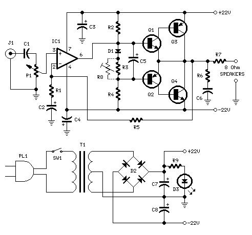
Power amplifier circuit diagram using the IC TLE2141C. The TLE2141C is a low-noise, high-voltage, high-slew-rate operational amplifier with a frequency response of 30 Hz. The TLE2141C operational amplifier is designed for applications requiring high precision and low noise, making it...
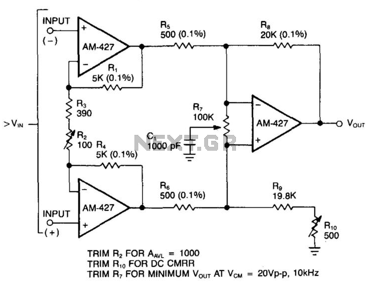
In a single difference amplifier configuration, the AM-427 demonstrates excellent common-mode rejection and low noise voltage, which is primarily influenced by the resistor Johnson noise. The three-amplifier configuration presented circumvents the low input-impedance characteristics typical of difference amplifiers. Due...
To get a low output impedance I needed to use quite a high step-down ratio (20:1); after all, the amplifier may be used with headphones of lower impedance than the 300 Ohms of the HD600. The output valve is...