
Tunable Crystal radio circuit
The described circuit is a basic crystal receiver designed to operate within the shortwave frequency band. The primary components of this circuit typically include a crystal diode, an inductor, a capacitor, and a pair of headphones as the output transducer. The crystal diode serves as the demodulator, allowing the circuit to convert high-frequency radio signals into audible sound.
The circuit operates by utilizing a tuned circuit formed by the inductor and capacitor, which resonates at the desired frequency of the incoming radio wave. This resonance amplifies the signal, making it more accessible for demodulation by the diode. The output from the diode is a low-level audio signal that can be directly fed into the headphones.
To enhance performance, the circuit may include a variable capacitor that allows tuning to different shortwave frequencies, enabling the user to select various stations. The headphones should be of high impedance to ensure compatibility with the low output power of the crystal receiver.
Overall, this simple crystal receiver circuit is an excellent project for beginners in electronics and radio communications, demonstrating fundamental principles of radio wave reception and audio signal processing.This is a very simple crystal reciever circuit for short wave band and can be used with headphones. 🔗 External reference
Related Circuits
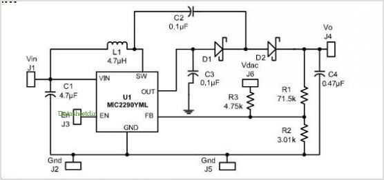
The MICRF112 is a high-performance, user-friendly, single-chip ASK/FSK transmitter integrated circuit (IC) designed for remote wireless applications within the 300 to 450 MHz frequency band. This transmitter IC features a true data-in, antenna-out configuration. The MICRF112 excels in three...
This compact device serves as a replacement for the input transistors and related circuitry on a single TO-220 style package. A decision was made to substitute the original driver board with a newly fabricated printed circuit board (PCB) designed...
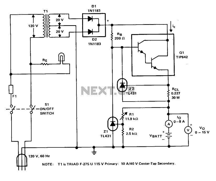
The charger operates with a charging voltage of 2.4 V per cell, aligning with the recommendations of most manufacturers. The circuit delivers a charging voltage of 14.4 V (6 cells at 2.4 V per cell) in a pulsed manner...
In 2003, the US Trade and Development Agency enhanced the performance of a device maintaining the same pin configuration as in 2002. The agency introduced additional functions in 2002 while ensuring a minimal number of external components, facilitating easy...
A gas leak detector circuit that detects the leakage of LPG gas and alerts the user through audio-visual indications. The circuit operates off a 9V PP3 battery. A Zener diode is used to convert 9V into 5V DC to...
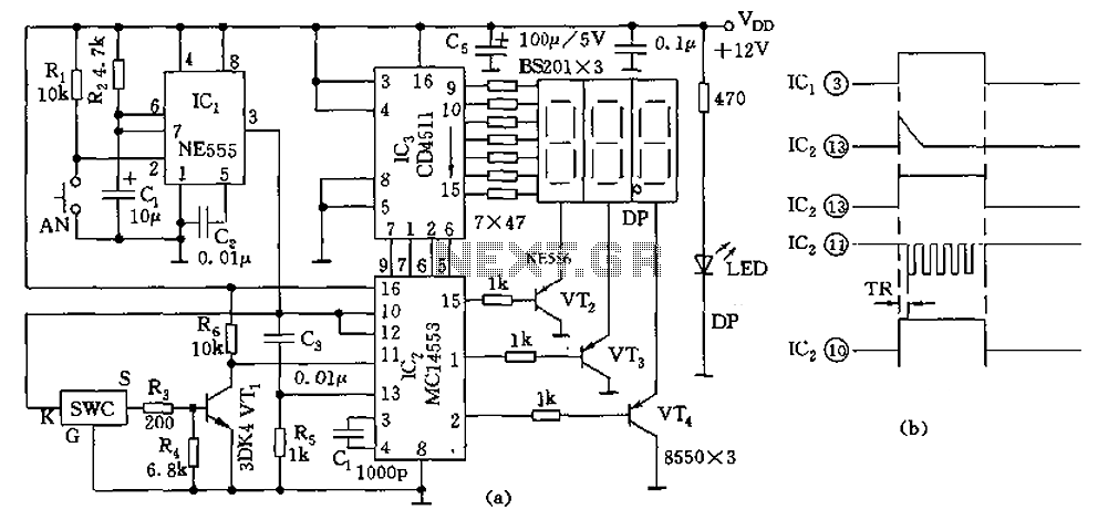
The digital thermometer consists of a temperature sensor, a single stabilizing circuit, a counter circuit, a decoding section, a driving circuit, and LED digital tubes among other components. It operates within a temperature range of 0 to 50 degrees...