
TV remote control blocker/jammer circuit diagram

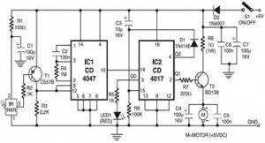
The described circuit utilizes a 555 timer integrated circuit (IC) in an astable configuration, generating a continuous square wave output. This output is at a frequency of approximately 38 kHz, which is critical for effectively jamming the IR signals from standard remote controls. The 555 timer's duty cycle can be adjusted by varying the resistances connected to pins 6 and 2, as well as the capacitor connected to pin 3, allowing for fine-tuning of the output signal.
The transistor in the circuit is used to amplify the current supplied to the infrared LEDs. By providing around 25 mA, the circuit ensures that the emitted IR light is strong enough to interfere with the remote control signals. Adjusting the resistor value will affect the current through the LEDs, thus influencing the range of the jamming effect. A lower resistance value increases the current and, consequently, the intensity of the emitted IR light, enhancing the range of the device.
The 10K potentiometer allows for real-time adjustments to the jamming frequency or intensity while the device is aimed at the television. This is crucial, as the effectiveness of the jamming can vary based on the specific remote control and television model. The trial-and-error method mentioned is a practical approach to find the optimal settings for the device to ensure that the remote control commands are effectively blocked.
It is important to note that the information provided is intended for personal use only, and any commercial application of this circuit should be approached with caution and requires prior permission from the authors of the original material. Additionally, the content is provided without guarantees, and users should be aware of potential copyright issues when utilizing or reproducing this information.Just point this small device at the TV and the remote gets jammed. The circuit is self explanatory. 555 is wired as an astable multivibrator for a frequency of nearly 38 kHz. This is the frequency at which most of the modern TVs receive the IR beam. The transistor acts as a current source supplying roughly 25mA to the infra red LEDs. To increas e the range of the circuit simply decrease the value of the 180 ohm resistor to not less than 100 ohm. It is required to adjust the 10K potentiometer while pointing the device at your TV to block the IR rays from the remote.
This can be done by trial and error until the remote no longer responds. Disclaimer: All the information present on this site are for personal use only. No commercial use is permitted without the prior permission from authors of this website. All content on this site is provided as is and without any guarantee on any kind, implied or otherwise. We cannot be held responsible for any errors, omissions, or damages arising out of use of information available on this web site.
The content in this site may contain COPYRIGHTED information and should not be reproduced in any way without prior permission from the authors. 🔗 External reference
Related Circuits
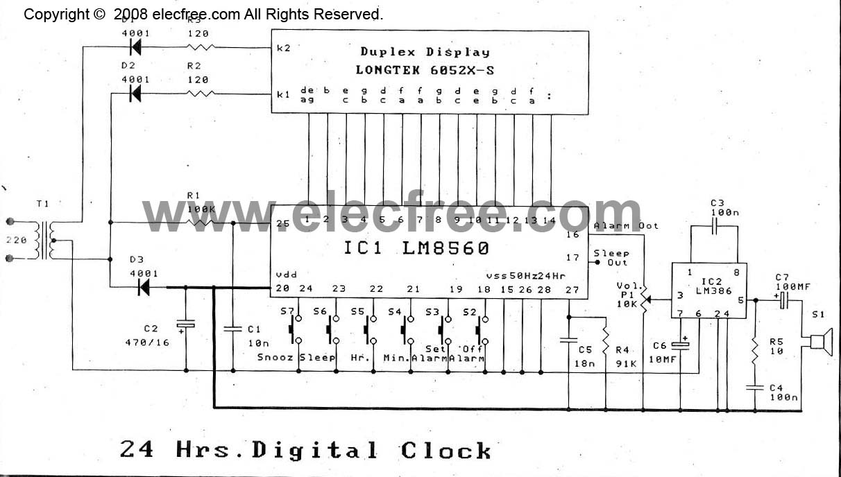
The digital time clock circuit is of great interest to electronic amateurs. The most popular clock ICs include the LM8361 and MM5387. Unfortunately, these ICs... The digital time clock circuit serves as an essential component for various electronic applications, providing...
This Wien bridge oscillator is straightforward and, like all Wien oscillators, exhibits low distortion. The resonance frequency can be easily adjusted. The Wien bridge oscillator is a type of electronic oscillator that generates sine waves. It is based on the principle...
The following circuit illustrates an Infrared Toy Car Motor Controller. This circuit is based on the 4047 and 4017 integrated circuits (ICs). Features include a 16V capacitor, a 100k resistor, and the use of dual ICs. Components involved are...
The objective is to enhance information transmission through the use of articles. Please contact us via email at [email protected] within 15 days if there are any issues related to article content, copyright, or other concerns. Prompt action will be...
The ultrasonic sensor circuit comprises a transmitter and a receiver, which are essential for remote control applications. The circuit operates at sound frequencies above 20 kHz, typically between 40 kHz and 50 kHz, powered by a 9V battery. When...

The following circuit is a PC thermometer utilizing the DS1621. Features include the ability to plug into any available PC COM port, a temperature range of -20 to 125°C, and the capability to display temperatures in both Celsius (°C)...