
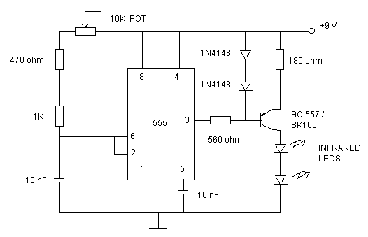
TV remote control Jamming circuit
It is required to adjust the 10K potentiometer while pointing the device at your TV to block the IR rays from the remote. This can be done by trial and error until the remote no longer responds.
The described device functions as an infrared (IR) jamming circuit designed to disrupt the communication between a remote control and a television set. The heart of the circuit is a 555 timer IC configured in an astable mode, which generates a continuous square wave signal at a frequency of approximately 38 kHz. This frequency is significant as it aligns with the modulation frequency used by most infrared remote controls, enabling the jamming device to effectively interfere with the signals sent by the remote.
In the circuit, the output of the 555 timer is connected to a transistor that acts as a switch, controlling the current flow to a series of infrared LEDs. These LEDs emit infrared light at the same frequency as the remote control signals, thereby saturating the receiver in the TV and preventing it from detecting the legitimate commands from the remote. The current supplied to the LEDs is approximately 25mA, which is sufficient to ensure that the emitted IR light is strong enough to effectively jam the remote control signals.
To enhance the operational range of the device, the 180-ohm resistor in the circuit can be adjusted. Lowering this resistor's value to no less than 100 ohms increases the current through the LEDs, thereby boosting the intensity of the emitted infrared light. This adjustment allows the jamming device to work effectively over a greater distance from the television.
Furthermore, the inclusion of a 10K potentiometer allows for fine-tuning of the circuit's output. By adjusting this potentiometer while aiming the device at the television, the user can modify the intensity of the jamming signal. This trial-and-error method enables the user to find the optimal setting at which the TV no longer responds to the remote control, thus confirming effective jamming.
Overall, this circuit serves as a practical example of using a 555 timer IC, a transistor, and infrared LEDs to create a device capable of interfering with IR communications, demonstrating fundamental principles of electronic design and circuit functionality.Just point this small device at the TV and the remote gets jammed . The circuit is self explanatory . 555 is wired as an astable multivibrator for a frequency of nearly 38 kHz. This is the frequency at which most of the modern TVs receive the IR beam . The transistor acts as a current source supplying roughly 25mA to the infra red LEDs. To increase the range of the circuit simply decrease the value of the 180 ohm resistor to not less than 100 ohm. It is required to adjust the 10K potentiometer while pointing the device at your TV to block the IR rays from the remote.
This can be done by trial and error until the remote no longer responds. 🔗 External reference
Related Circuits
This document describes a simple triac tester circuit that can also be utilized for testing silicon-controlled rectifiers (SCRs) and both PNP and NPN transistors. The circuit operates on 3V DC, which can be derived from a Zener diode combined...
An automatic humidifier can be utilized for humidity control in households, hatcheries, poultry farms, or juvenile poultry houses. When the humidity level falls below 50%, the automatic humidifier activates to maintain a specific humidity level that is beneficial for...
This is a simple yet effective darkness activator. It uses a light-dependent resistor (LDR) to detect light, and when no light is present, it activates an alarm from an 8-ohm speaker. The circuit can be easily modified to function...
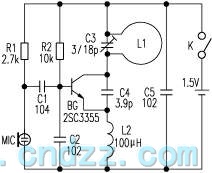
The loop antenna L1 is utilized for emission and also functions as the oscillation coil. The high-frequency current flowing through the antenna is synchronized in resonance with the oscillation frequency, ensuring optimal emission performance. Practical applications indicate that the...
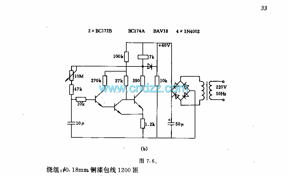
The circuit features a two-stage structure with a timing range of approximately 0.5 to 12 seconds, while in a specified configuration, the timing range extends from 1 to 160 seconds. The transformer parameters include an iron core made of...
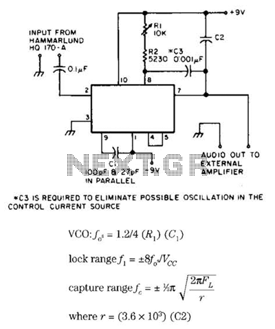
Useful for narrowband frequency modulation (NBFM) reception on older shortwave receivers that lack this capability, this circuit employs a phase-locked loop (PLL) integrated circuit, specifically the N565N. It was originally designed for use with an old Hammarlund HQ-170 receiver,...