
Simple long-distance wireless FM microphone circuit
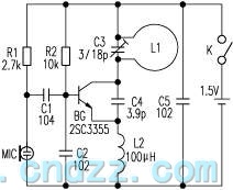
The loop antenna, designated as L1, plays a dual role in this circuit design. It not only serves as the primary emission component but also acts as the oscillation coil, contributing to the overall functionality of the device. The design takes advantage of the principle of resonance, where the high-frequency current that circulates within the loop antenna is carefully tuned to match the oscillation frequency of the system. This synchronization is critical as it maximizes the efficiency of the antenna, allowing it to operate in an optimal emission state.
In practical scenarios, such as in an empty mine environment, the loop antenna has demonstrated a launching distance of approximately 100 to 150 meters. This range can be influenced by various factors, including the surrounding environment, the presence of obstacles, and the specific parameters of the oscillation frequency and current.
For enhanced performance, the design may incorporate additional components such as tuning capacitors and inductors to fine-tune the resonance conditions. The careful selection of materials for the antenna and its configuration can also significantly impact the efficiency and range of the emitted signal. A well-designed loop antenna can achieve a balance between size, weight, and performance, making it suitable for various applications where reliable communication over distances is required.
To further optimize the system, considerations regarding the impedance matching between the antenna and the transmitter circuit may be necessary. This ensures that maximum power transfer occurs, thereby enhancing the overall effectiveness of the emission system. Additionally, the implementation of feedback mechanisms could be explored to maintain the resonance condition dynamically, adapting to variations in environmental conditions or operational parameters.The the loop antenna L1 for emission also serves as the oscillation coil, the high-frequency current flowing in antenna is synchronized resonance with the oscillation frequency, so it is always in the best emission state. Accoring to practice, launching distance is about 100 ~ 150m in empty mine. In contrast, in the case of equal working voltage, current and.. 🔗 External reference
Related Circuits
The calibration circuit operates in inject mode, generating a square wave output in the audio range, where power harmonics can be detected at several Hertz. In tracking mode, the amplifier detects non-linear operation by filtering a modulated RF signal...
The circuit employs two Light Dependent Resistors (LDRs) arranged in series with a separation of approximately half a meter. This configuration allows each LDR to detect the presence of a person entering or exiting the room. The processed outputs...
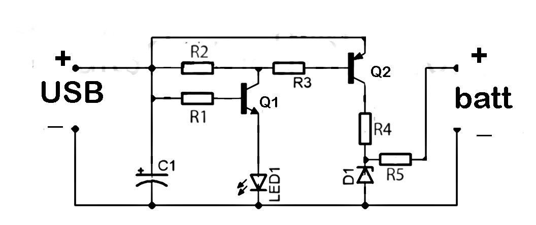
This document discusses the series used in USB connections for charging batteries. The output voltage ranges from 4.7 volts to 5 volts DC, which is suitable for charging mobile phones and other battery types. The circuit described enhances the...
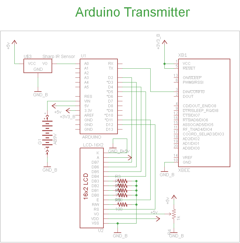
The schematic for the transmitter in this project consists of four main components: the Arduino UNO, the Sharp IR distance sensor, the XBee wireless modules, and a 16x2 LCD. The connections between these components are illustrated in the schematic....
Before applying power, check for shorts on the board. This design operates from a 5V supply; connecting it directly to a 12V supply will certainly damage it. The current draw is minimal, approximately 70mA, so if using a 12V...
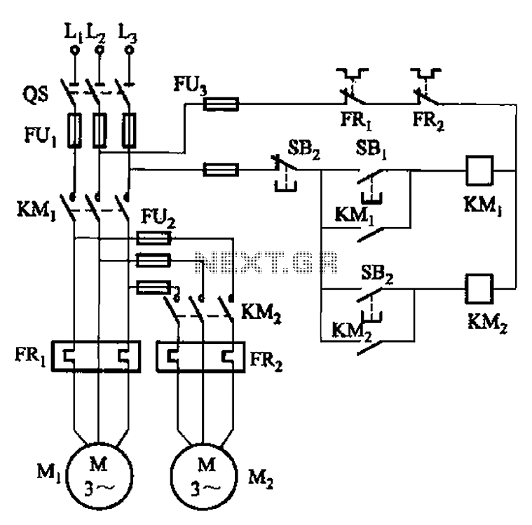
The circuit illustrated in Figure 3-83 demonstrates that the contactor KMi is activated only after it is pulled, which indicates that the motor Mi has started for the first time. Following this, the contactor KM2 is then activated, indicating...