
tv transmitter circuit

The described TV transmitter circuit operates within the VHF frequency range, making it suitable for short-range broadcasting applications. The primary components include a transistor, which serves as the active amplification element, and an inductor, which is crucial for tuning the circuit to the desired frequency. The choice of transistor—BC337, N2222, BC546, or BC108—provides flexibility in component selection based on availability and performance characteristics. Each of these transistors has suitable gain and frequency response for this application.
The inductor L1, wound with six turns of #24 enameled wire on a 10 mm air former, is essential for the oscillation and frequency stability of the transmitter. The number of turns and the diameter of the former directly influence the inductance value, which in turn affects the resonant frequency of the circuit. It is important to ensure that the inductor is properly constructed to minimize losses and maintain efficiency.
The output power of 80 mW is adequate for local transmission, and the use of a telescopic antenna enhances the range and quality of the broadcast signal. The antenna's design should be matched to the operating frequency to optimize performance. Proper grounding and shielding techniques should be employed to minimize interference and enhance signal clarity.
In summary, this simple VHF transmitter circuit is a practical solution for low-power video broadcasting, suitable for hobbyists and educational purposes. Careful attention to component selection, circuit layout, and tuning will result in an effective and functional transmitter capable of delivering quality video signals within the specified frequency range.Here`s a simple schematic of a TV transmitter circuit or video transmitter circuit which is able to broadcast on VHF between 60 to 200 MHz. The input video can be from any CCD camera and VCR. The output power of this VHF transmitter circuit is 80mW and by using telescopic antenna this The circuit is using only one transistor that can be a BC337, 2
N2222, BC546 or BC108. For L1 wound 6 turns of #24 enameled wire on a 10mm air former for frequency 60 - 80 MHz. 🔗 External reference
Related Circuits
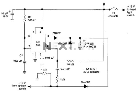
When the ignition switch is activated, relay K1 receives continuous power, allowing the headlights to be turned on. When the ignition is turned off, timer IC1 is activated, maintaining its power for a duration determined by resistor R1 and...

Personal Safes are revolutionary locking storage cases that open with just the touch of your finger. These products are designed as secure storage for medications, jewelry, weapons, documents, and other valuable or potentially harmful items. These utilize fingerprint recognition...
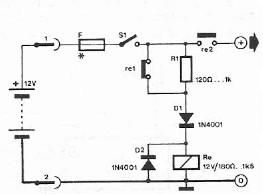
Safety polarity connection circuit design using common electronic components The safety polarity connection circuit is designed to ensure that electronic devices are connected with the correct polarity, preventing damage from reversed connections. This circuit typically employs common electronic components such...
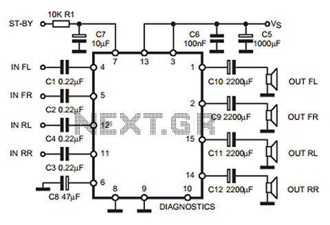
The following circuit illustrates a 35W quadruple amplifier and a 2 x 25W bridge amplifier based on the TDA7375 integrated circuit (IC). This circuit requires a minimal number of external components. Although initially designed for car applications, it can...
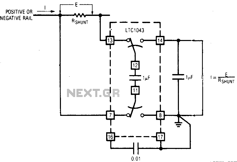
The LTC1043 can be induced through any of its current shunt supply rails. Many cells and solar system applications have this feature. If the reference point is grounded, the voltage output of an unloaded amplifier is minimal, allowing the...
This is a VU meter analog circuit. The circuit is connected to the line terminals of the amplifier. The VU meter operates simply, with T1 and T2 indicating signal increases. The VU meter circuit is designed to visually represent audio...