
Safety polarity connection circuit
The safety polarity connection circuit is designed to ensure that electronic devices are connected with the correct polarity, preventing damage from reversed connections. This circuit typically employs common electronic components such as diodes, resistors, and transistors to create a protective mechanism.
The core of the circuit often includes a diode placed in series with the power supply. This diode allows current to flow in the correct direction while blocking reverse polarity. In addition, a second diode may be used in parallel with the load, oriented to conduct during reverse polarity conditions, thereby protecting sensitive components from damage.
Resistors can be incorporated to limit the current flowing through the diodes, ensuring they operate within safe parameters. Furthermore, a visual indicator, such as an LED, may be added to signal correct polarity. This LED would be connected in such a way that it illuminates when the circuit is correctly powered, providing immediate feedback to the user.
In more complex designs, a transistor can be utilized to enhance the circuit's functionality. For example, a transistor can be configured to act as a switch that disconnects the load in the event of incorrect polarity, adding an additional layer of protection.
Overall, the safety polarity connection circuit is a fundamental design that leverages widely available components to enhance the reliability and safety of electronic devices, making it an essential consideration in circuit design.Safety polarity connection circuit design using common electronic components 🔗 External reference
Related Circuits
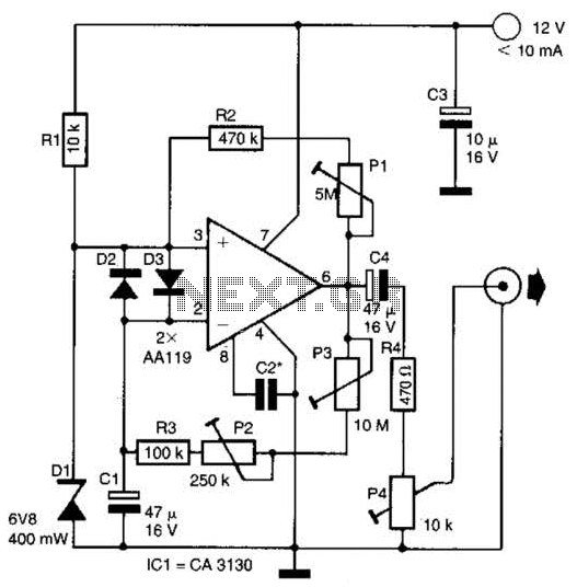
This circuit generates noise pulses suitable for test purposes. A Zener diode serves as the noise source. IC1 functions as a relaxation oscillator. P1 determines the noise bandwidth, while P2 and P3 control the noise amplification. The current consumption...
Research has been conducted on a project aimed at enhancing understanding of electronics, networking, and programming. The project involves the construction of an online thermometer suitable for applications requiring temperature monitoring. The current work environment is a laboratory where...

Zilog's Z8 Encore XP F1680 Series features a highly optimized set of capabilities specifically designed for stepper motor microstepping control. Key features of the Z8 Encore! XP F1680 include: an 11 MHz internal oscillator, two analog comparators, a 10-bit...
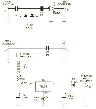
This wideband amplifier circuit is designed using the MAR-6 IC manufactured by Mini Circuits. The MAR-6 VHF-UHF wideband amplifier circuit provides a stable gain of at least 9 dB up to 2 GHz. Since the MAR-6 is designed to...
For example, I do not understand the process of demodulation or the modulation itself, and so on. Is there someone who can understand this circuit? Could you please assist me? The circuit in question likely involves a modulation and demodulation...
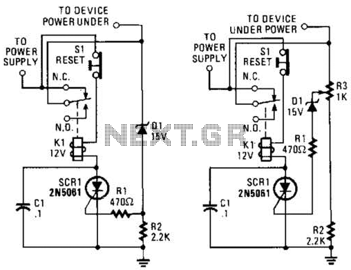
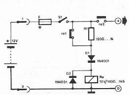
If circuits experience frequency overvoltage conditions, continually replacing blown fuses can become quite costly. This shutdown circuit addresses that issue by substituting the fuse with a relay and a low-current SCR. When the input voltage exceeds the threshold established...