
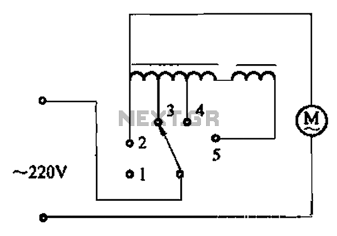
Two inverter controlled synchronous motor of the second circuit
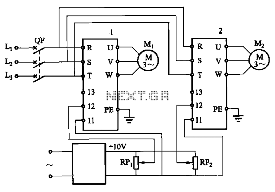
The circuit utilizes two potentiometers, designated as RPi and RPz, to control the speed of two separate motors. Each potentiometer is connected in a voltage divider configuration, enabling variable resistance that affects the voltage supplied to the motor drivers.
The motor drivers, which can be either H-bridges or simple transistor-based circuits, receive the adjusted voltage from the potentiometers. As the resistance of RPi and RPz is varied, the output voltage changes accordingly, allowing for precise control over the speed of each motor.
To implement this design, the following components are typically used:
- Two potentiometers (RPi and RPz) with suitable resistance values to ensure effective control over the motor speed.
- Two motor driver circuits capable of handling the current and voltage requirements of the motors.
- Power supply to provide the necessary voltage to the motors and the driver circuits.
- Motors that are compatible with the chosen driver circuit specifications.
Wiring should be done such that the wiper of each potentiometer connects to the input of the respective motor driver, while the other two terminals connect to the power supply and ground. This arrangement allows for smooth and responsive speed adjustments based on the potentiometer settings.
In summary, this circuit design effectively integrates potentiometers for variable motor speed control, providing flexibility and precision in applications requiring adjustable motor performance.Adjust potentiometer RPi and RPz, two motor speed can be changed.
Related Circuits
Every dedicated DIY enthusiast creates their own electronic dice using LEDs as indicators. This eliminates the need to physically roll dice; simply pressing a button activates the electronic mechanism. The design incorporates safeguards to prevent manipulation for improved outcomes,...
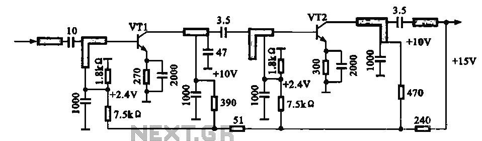
An IF pre-amplifier circuit is presented in a distributed-parameter microstrip configuration. It operates within the frequency range of 950 to 1,470 MHz. The output impedance is approximately 75 ohms. The power supply for the circuit is connected to the...
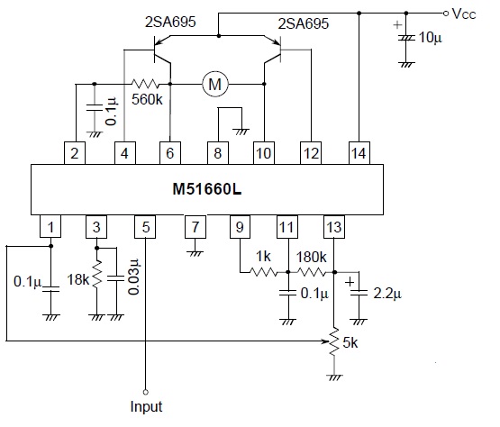
A servo is a compact motor capable of precise positioning at various angles. It incorporates internal circuitry designed to maintain its position automatically. A servo motor typically consists of a DC motor, a gear system, a potentiometer, and a control...
Voltage regulator ICs from the 78xx series deliver a stable output voltage in contrast to a highly variable input supply, provided that the common terminal is grounded. Any voltage applied above zero volts (ground) to the common terminal is...
A stepper motor controller is required to operate a stepper motor, as a stepper motor cannot function merely by connecting it to a power supply. A stepper motor controller is an essential component for the effective operation of stepper...
The circuit illustrated in Figure 3-2 features a loop reactor governor that incorporates a series reactor. The reactor can be constructed using a TV choke and is designed to be approximately 3mm in height. It utilizes a strength wire...
Warning: include(partials/cookie-banner.php): Failed to open stream: Permission denied in /var/www/html/nextgr/view-circuit.php on line 713
Warning: include(): Failed opening 'partials/cookie-banner.php' for inclusion (include_path='.:/usr/share/php') in /var/www/html/nextgr/view-circuit.php on line 713